


9
4. Gas supply pipe must be located within the shaded area as
shown in the “Cabinet Dimensions” illustration in “Location
Requirements” section.
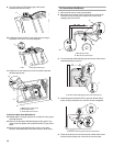
Complete connection
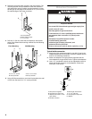
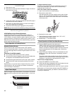
1. Open the manual shutoff valve in the gas supply line. The
valve is open when the handle is parallel to the gas pipe.
2. Test all connections by brushing on an approved
noncorrosive leak-detection solution. If bubbles appear, a
leak is indicated. Correct any leak found.
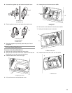
3. Remove cooktop burner caps and grates from parts
package. Align recess in burner caps with pins in burner
base. Burner caps should be level when properly positioned.
If burner caps are not properly positioned, surface burners
will not light. Place burner grates over burners and caps.
4. Plug into a grounded 3 prong outlet.
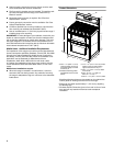
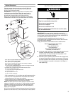
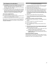
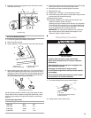
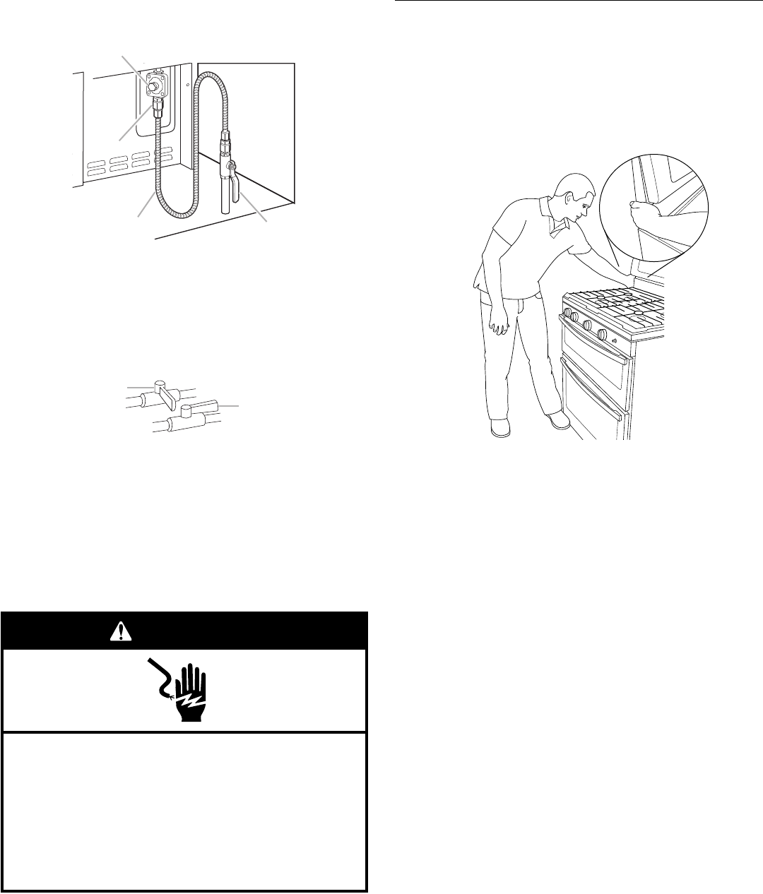
Verify Anti-Tip Bracket Is Installed and
Engaged
1. Place the outside of your foot against the bottom front of the
oven door to keep the unit from moving, and grasp the lower
right or left side of the control panel as shown.
NOTE: If your countertop is mounted with a backsplash, it
may be necessary to grasp the range higher than is shown in
the illustration.
2. Slowly attempt to tilt the range forward.
If you encounter immediate resistance, the range foot is
engaged in the anti-tip bracket.
3. If the rear of the range lifts more than ½" (1.3 cm) off the floor
without resistance, stop tilting the range and lower it gently
back to the floor. The range foot is not engaged in the anti-tip
bracket.
IMPORTANT: If there is a snapping or popping sound when lifting
the range, the range may not be fully engaged in the bracket.
Check to see if there are obstructions keeping the range from
sliding to the wall or keeping the range foot from sliding into the
bracket. Verify that the bracket is held securely in place by the
mounting screws.
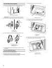
4. Slide the range forward, and verify that the anti-tip bracket is
securely attached to the floor or wall.
5. Slide range back so the rear range foot is inserted into the
slot of the anti-tip bracket.
IMPORTANT: If the back of the range is more than 2" (5.1 cm)
from the mounting wall, the rear range foot may not engage the
bracket. Slide the range forward and determine if there is an
obstruction between the range and the mounting wall. Changes
to the gas supply must be performed by a qualified service
technician. If you need assistance or service, refer to the
“Assistance or Service” section of the Use and Care Guide, or the
cover or “Warranty” section of the User Instructions, for contact
information.
6. Repeat steps 1 and 2 to ensure that the range foot is
engaged in the anti-tip bracket.
If the rear of the range lifts more than ½" (1.3 cm) off the floor
without resistance, the anti-tip bracket may not be installed
correctly. Do not operate the range without anti-tip bracket
installed and engaged. Please reference the “Assistance or
Service” section of the Use and Care Guide, or the cover or
“Warranty” section of the User Instructions, to contact
service.
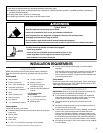
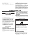
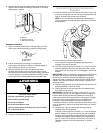
A.Gas pressure regulator
B.Adapter
C.Flexible connector
D.Manual shutoff valve
A.Closed valve
B.Open valve
Adaptor
A
B
C
D
A
B
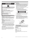
Electrical Shock Hazard
Plug into a grounded 3 prong outlet.
Do not remove ground prong.
Do not use an adapter.
Do not use an extension cord.
Failure to follow these instructions can result in death,
fire, or electrical shock.
WARNING