


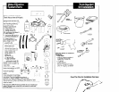
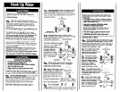
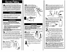
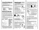
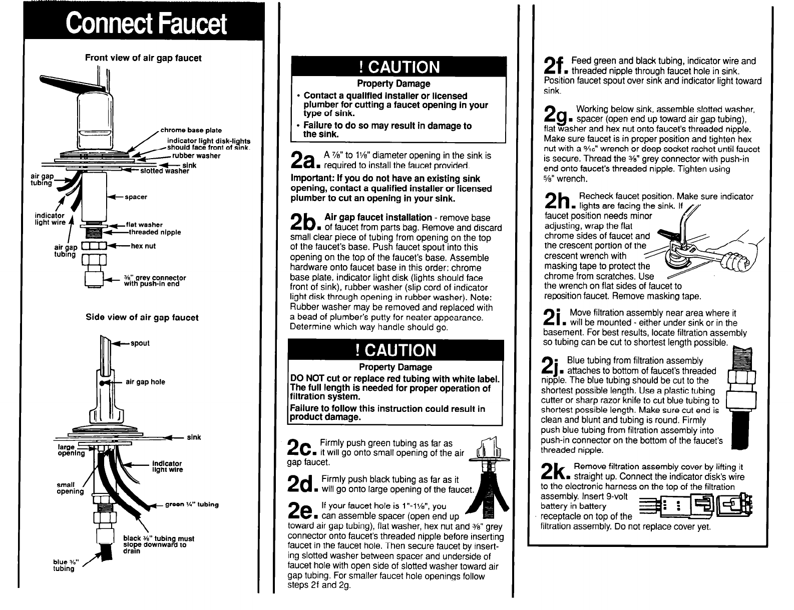
Front view of air gap faucet
_ chrome base elate
indicator -
light wire
t
;fby;; Fhex nut
Is-
%” grey connector
with push-in end
Side view of air gap faucet
k
spout
air gap hole
slnk
%” tubing
black %” tubing must
;lor; downward to
blue %”
tubing
Property Damage
l
Contact a qualified installer or licensed
plumber for cutting a faucet opening in your
type of sink.
l
F!;IIwJ~ do so may result in damage to
2a
A 741” to 1%” diameter opening in the sink is
. required to install the faucet provided.
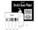
Important: If you do not have an existing sink
opening, contact a qualified installer or licensed
plumber to cut an opening in your sink.
2b
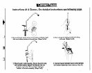
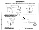
Air gap faucet installation - remove base
. of faucet from parts bag. Remove and discard
small clear piece of tubing from opening on the top
of the faucet’s base. Push faucet spout into this
opening on the top of the faucet’s base. Assemble
hardware onto faucet base in this order: chrome
base plate, indicator light disk (lights should face
front of sink), rubber washer (slip cord of indicator
light disk through opening in rubber washer). Note:
Rubber washer may be removed and replaced with
a bead of plumber’s putty for neater appearance.
Determine which way handle should go.
Property Damage
DO NOT cut or replace red tubing with white label.
The full length is needed for proper operation of
filtration system.
Failure to follow this instruction could result in
product damage.
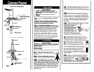
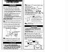
2c
Firmly push green tubing as far as
. it will go onto small opening of the air
gap faucet.
2d
Firmly push black tubing as far as it
. will go onto large opening of the faucet.
2e
If your faucet hole is 1 “-I%“, you
H can assemble spacer (open end up
toward air gap tubing), flat washer, hex nut and 3/e” grey
connector onto faucet’s threaded nipple before inserting
faucet in the faucet hole. Then secure faucet by insert-
ing slotted washer between spacer and underside of
faucet hole with open side of slotted washer toward air
gap tubing. For smaller faucet hole openings follow
steps 2f and 29.
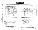
2f
Feed green and black tubing, indicator wire and
n
threaded nipple through faucet hole in sink.
Position faucet spout over sink and indicator light toward
sink.
29
Working below sink, assemble slotted washer,
. spacer (open end up toward air gap tubing),
flat washer and hex nut onto faucet’s threaded nipple.
Make sure faucet is in proper position and tighten hex
nut with a %6” wrench or deep socket rachet until faucet
is secure. Thread the Y811 grey connector with push-in
end onto faucet’s threaded nipple. Tighten using
76” wrench.
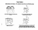
2h
Recheck faucet position. Make sure indicator
. lights are facing the sink. I
faucet position needs minor
adjusting, wrap the flat
chrome sides of faucet
the crescent portion of
crescent wrench with
masking tape to protect th
chrome from scratches.
Use
the wrench on flat sides of faucet to
reposition faucet. Remove masking tape.
.
21
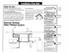
Move filtration assembly near area where it
. will be mounted - either under sink or in the
basement. For best results, locate filtration assembly
so tubing can be cut to shortest length possible.
Blue tubing from filtration assembly
. attaches to bottom of faucet’s threaded
The blue tubino should be cut to the
shortest possible lengih. Use a plastic tubing
cutter or sharp razor knife to cut blue tubing to
shortest possible length. Make sure cut end is
clean and blunt and tubing is round. Firmly
push blue tubing from filtration assembly into
push-in connector on the bottom of the faucet’s
threaded nipple.
5
ig it
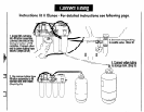
2k
Remove filtration assembly cover by liftir
. straight up. Connect the indicator disks wrre
to the electronic harness on the too of the filtration
assembly. Insert g-volt
battery in battery
receptacle on top of the
filtration assembly. Do not replace cover yet.