


— 6 —
GAS CONNECTIONS
CAUTION: All gas supply connections and any pipe joint compound used must be
resistant to the action of propane gases.
WARNING: PRIOR TO LIGHTING, CHECK ALL JOINTS IN THE GAS SUPPLY LINE FOR
LEAKS. USE SOAP AND WATER SOLUTION. DO NOT USE AN OPEN FLAME.
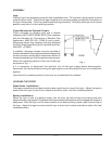
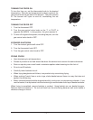
Rear Gas Connection for Stand Alone Installations
The gas inlet is located at the lower left rear.
Codes require that a gas shutoff valve be installed in the gas line ahead of the fryer.
The gas supply line must be at least the equivalent of
1
/2" (12.7 mm) iron pipe. If using the optional
quick-disconnect flex hose,
3
/4" (19 mm) iron pipe must be used unless
3
/4" (19 mm) to
1
/2" (12.7 mm)
reducing fittings are used. Make sure the pipes are clean and free of obstructions, dirt, and piping
compound.
After piping has been checked for leaks, all piping receiving gas should be fully purged to remove
air.
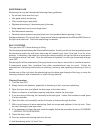
Front Gas Connection for Battery Installations
Codes require that a gas shutoff valve be installed in the gas line ahead of the fryer and battery of
equipment.
The gas manifold of a battery lineup of which the fryer is a part, must be installed using a regulator
design-certified by a nationally recognized testing lab to the applicable ANSI standard. The
pressure regulator must have a maximum regulation capacity to handle the total connected load and
must have an adjustment range for manifold pressure marked on the equipment rating plate(s). If
the manifold pressure of the connected equipment is not the same, a separate regulator must be
supplied for all devices operating under different manifold pressure ratings.
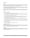
CONNECTION OF MANIFOLDS IN BATTERY
1. If the fryer requires alignment to match the battery lineup, remove the front panel and door
assembly. Start fryer alignment by loosening 2 bolts on each U bracket securing the 1
1
/4" (31.8
mm) manifold pipe to the fryer.
2. Shift the 1
1
/4" (31.8 mm) manifold pipe left or right, in or out, until alignment with the equipment
battery manifold pipe is achieved. While holding the fryer manifold in place, tighten the holding
screws on the U bracket back in place.
3. Apply pipe sealer resistant to the action of propane gases around the threaded edge(s) of the
fryers 1
1
/4" (31.8 mm) manifold pipe.
4. Engage the union nut on the fryer manifold pipe with the male fitting on the batteried unit
adjacent to the fryer. Draw up the union hand tight. Continue connecting the manifolds, following
these steps 1 - 4, until all units in the battery lineup are installed.
5. Using channel locks, tighten all connection points along the manifold of the entire equipment
battery.
6. Install manifold end cap if applicable.
7. Check all connection points along the manifold for gas leaks.