


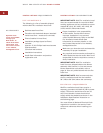
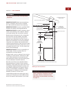
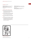
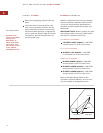
Run a 120 V AC, 15 amp circuit (minimum)
p
ower cable from the service panel to the
electrical box in the back of the hood liner.
I
nsert the conduit through the holes in the
back of the hood liner to the electrical box.
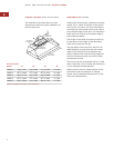
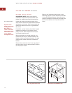
Remove the electrical box cover from the
back of the hood liner. Connect black wire
to power supply black wire, white wire to
power supply white wire and green wire to
green wire or bare wire.
Place all wiring connections inside the
electrical box and reinstall the electrical box
cover. Make sure that the wires are secure
and that no wires are pinched between the
cover and box.
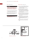
Refer to the wiring diagram packaged with the
hood liner for more information.
10
WOLF PRO VENTILATION HOOD LINERS
INSTALL WIRING
This ventilation hood liner must be
properly grounded and should be installed
by a qualified electrician in accordance
with all applicable national and local
electrical codes.
Before servicing or cleaning, switch
power off at service panel and lock the
service disconnecting means to prevent
power from being switched on acciden-
tally. When the service disconnecting
means cannot be locked, securely fasten
a prominent warning device, such as a
tag, to the service panel.
IMPORTANT
NOTE
You must follow
all National
Electrical Code
regulations. In
addition, be aware
of local codes and
ordinances when
installing your
service.
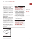
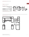
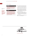
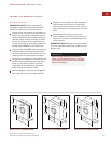
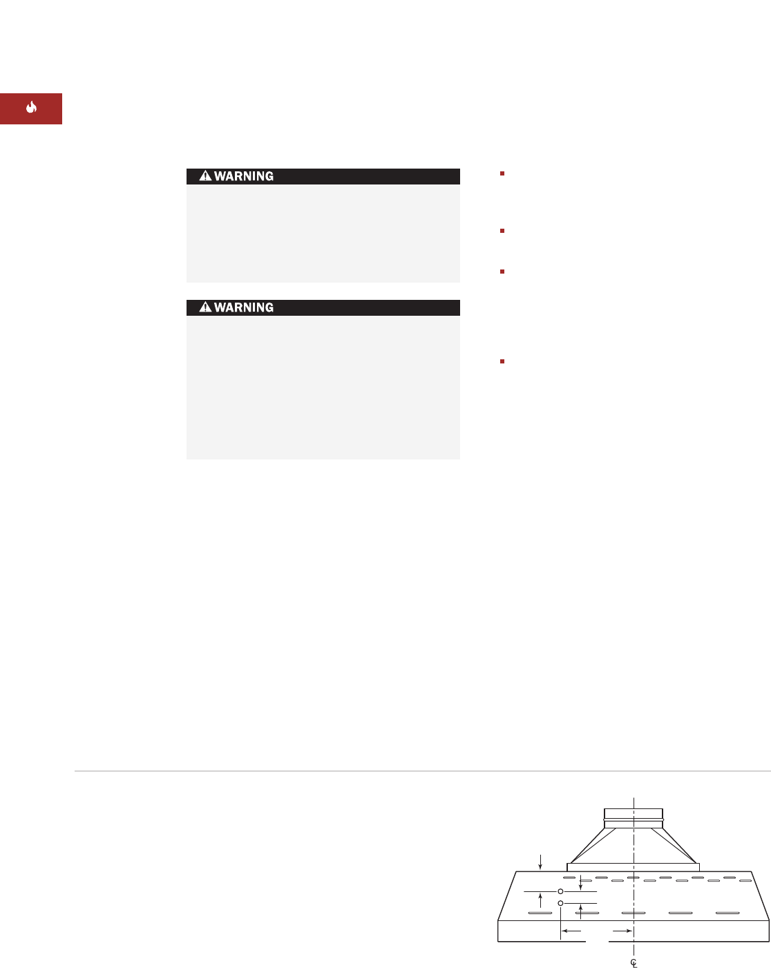
1
7
/8"
(
48
)
3
1
/2" (89)
12
1
/2"
(318)
Pro hood liner wiring location