


Installation
Warning! The following instructions about
installation, connection and maintenance must be
carried out by qualified personnel in compliance with
standards and local regulations in force.
Important safety requirements
This hob must be installed in accordance with the Gas
Safety (Installation and Use) Regulations (Current Edition)
and the IEE Wiring Regulations (Current Edition).
For appliances installed in the Republic of Ireland please
refer to NSAI- Domestic Gas Installation I.S. 813 Current
Editions and the ETCI Rules for Electrical Installations.
Provision for ventilation
Detailed recommendations are contained in the following
British Standards Codes Of Practice: B.S. 6172/ B.S.
5440, Par. 2 and B.S. 6891 Current Editions.
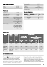
The hob should not be installed in a bed sitting room with
a volume of less than 20 m³. If it is installed in a room of
volume less than 5 m³ an air vent of effective area of 100
cm² is required. If it is installed in a room of volume be-
tween 5 m³ and 10 m³ an air vent of effective area of 50
cm² is required, while if the volume exceeds 11 m³ no air
vent is required.
However, if the room has a door which opens directly to
the outside no air vent is required even if the volume is
between 5 m³ and 11 m³.
If there are other fuel burning appliances in the same
room, B.S. 5440 Part 2 Current Edition, should be consul-
ted to determine the requisite air vent requirements.
For appliances installed in the Republic of Ireland please
refer to the NSAI- Domestic Gas Installation I.S. 813 Cur-
rent Editions Table Four.
Location
The hob may be located in a kitchen, a kitchen/diner or
bed sitting room (with a volume greater than 20 m³), but
not in a bathroom or shower room.
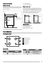
The minimum distance combustible material can be fitted
above the hob in line with the edges of the hob is 400
mm. If it is fitted below 400 mm a space of 50 mm must
be allowed from the edges of the hob.
For appliances installed in the Republic of Ireland please
refer to NSAI- Domestic Gas Installation I.S 813 Current
Edition Section 7- Permitted Locations of Appliance.
Gas Connection
Warning! Any gas installation must be carried out
by a GAS SAFE REGISTER installer.
Make sure that, once the hob is installed, it is easily ac-
cessible for the engineer in the event of a breakdown.
The manufacturer will not accept liability, should the
above instructions or any of the other safety instructions
incorporated in this instruction booklet be ignored.
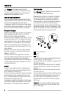
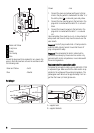
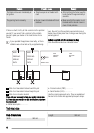
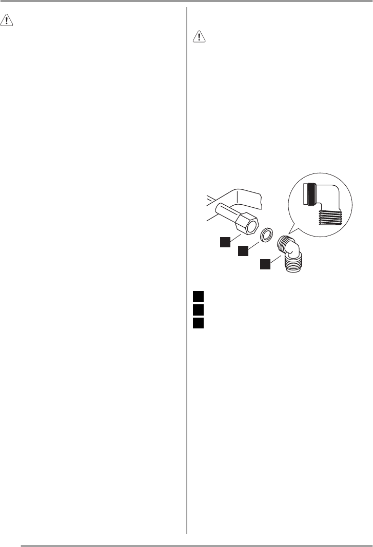
On the end of the shaft, which includes the G 1/2" threa-
ded elbow, adjustment is fixed so that the washer is fitted
between the components as shown in the diagram. Screw
the parts together without using excessive force.
1
2
3
1 End of shaft with nut
2 Washer
3 Elbow
Connection to the gas supply should be with either rigid
or semi-rigid pipe, i.e. steel or copper.
The connection should be suitable for connecting to R 1/2
(1/2 BSP male thread).
When the final connection has been made, it is essential
that a thorough leak test is carried out on the hob and in-
stallation.
Make sure that the main connection pipe does not exert
any strain on the hob.
If you use flexible metal pipes make sure that they agree to
ISO 10380 and ISO 10807 standards. Be careful they do
not come in touch with mobile parts or they are not
squeezed. Also be careful when the hob is put together
with an oven.
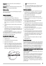
Important! It is important to install the elbow correctly,
with the shoulder on the end of the thread, fitted to the
hob connecting pipe.
4