


Important! Failure to ensure the correct assembly will
cause leakage of gas.
Important! Make sure that the gas supply pressure of the
appliance obeys the recommended values.
Rigid connection:
Carry out connection by using metal rigid pipes (copper
with mechanical end).
Injectors replacement
1. Remove the pan supports.
2. Remove the caps and crowns of the burner.
3. With a socket spanner 7 remove the injectors and re-
place them with the ones which are necessary for the
type of gas you use (see table in Technical Data sec-
tion).
4. Assemble the parts, follow the same procedure back-
wards.
5. Replace the rating label (it is near the gas supply
pipe) with the one for the new type of gas supply. You
can find this label in the package of the injectors sup-
plied with the appliance.
If the supply gas pressure is changeable or different from
the necessary pressure, you must fit an applicable pres-
sure adjuster on the gas supply pipe.
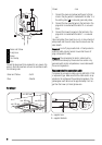
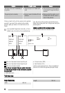
Adjustment of minimum level
To adjust the minimum level of the burners:
1. Light the burner.
2. Turn the knob on the minimum position.
3. Remove the control knob.
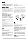
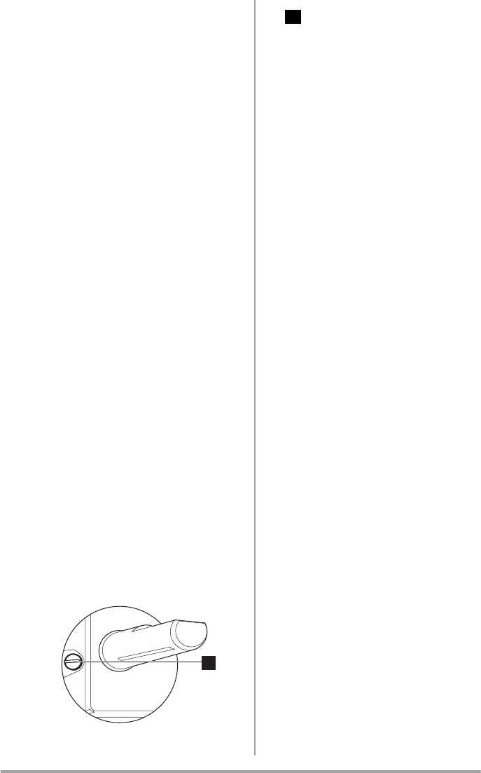
4. With a thin screwdriver, adjust the by-pass screw po-
sition. If you change from natural gas 20 mbar to liq-
uid gas, fully tighten the adjustment screw in. If you
change from liquid gas to natural gas 20 mbar, undo
the by-pass screw approximately 1/4 of a turn.
1
1
Minimum adjustment screw
5. Make sure the flame does not go out when you quick-
ly turn the knob from the maximum position to the
minimum position.
Electrical connection
• Any electrical work required to install this hob should
be carried out by a qualified electrician or competent
person, in accordance with the current regulations.
• THIS HOB MUST BE EARTHED.
• Always use a correctly installed shockproof socket.
• Make sure that there is an access to the mains plug af-
ter installation.
• Do not pull the mains cable to disconnect the appli-
ance. Always pull the mains plug.
• The appliance must not be connected with an extension
cable, an adapter or a multiple connection (risk of fire).
Check that the ground connection is in conformity with
the standard and regulations force.
• The power cable must be placed in such a way that it
does not touch any hot part.
• Connect the appliance to the mains with a device that
lets to disconnect the appliance from the mains at all
poles with a contact opening width of minimum 3 mm,
eg. automatic line protecting cut-out, earth leakage
trips or fuse.
• None of a parts of the connection cable can not get a
temperature 90°C.
Electrical Requirements
Any permanent electrical installation must comply with the
latest I.E.E. Regulations and local Electricity Board regula-
tions. For your own safety this should be undertaken by a
qualified electrician, e.g. your local Electricity Board, or a
contractor who is on the roll of the National Inspection
Council for Electrical Installation Contracting (NICEIC).
The manufacturer declines any liability should these safety
measures not be observed.
This hob is designed to be connected to a 230 V 50 Hz AC
electrical supply.
Before switching on, make sure the electricity supply volt-
age is the same as that indicated on the hob rating plate.
The rating plate is located on the bottom of the hob.
The hob is supplied with a 3 core flexible supply cord in-
corporating a 3 amp plug fitted. In the event of having to
change the fuse, a 3 amp ASTA approved (BS 1362) fuse
must be used.
5