On completion check that the base is stable
even if the frame is subject to movement.
The installer must provide ample
support where the ceiling or support
shelf is not strong enough by
installing cross beams over the joists
or above the shelf to ensure the
frame is quite rigid at its mounting
point.
Extraction
The cooker hood is more effective when used in the
extraction mode (ducted to the outside).
Venting kits may be purchased through your
retailer or DIY store, and must be ducted to an
outside vent of Ø125mm (5”) or Ø150mm (6”).
For the best performance use the shortest possible
duct run and the minimum number of bends.
Where flexible ducting is fitted it should not be turned
through very tight bends as this may impair the
performance of the hood.
It is recommended a maximum length of 3 metres
with one bend, to be installed, to be reduced metre
for each 90o bend.
If a distance is greater than 3 metres the efficiency
of the hood could be impaired.
The ducting used must be manufactured
from fire retardent material conforming to the
relevant British Standard or DIN 4102-B1.
When the cooker hood is ducted to the outside the
charcoal filter must be removed.
Ducting Connection
Connect the ducting chosen to:
the Ø150mm ducting spigot on top of the
motor housing, or the Ø150-120mm ducting
spigot 9 and secure using the jubilee clips
25.
A Ø120-125mm collar 10 is provided
to fit over the Ø120mm ducting spigot
when 125mm ducting is fitted.
If the room where the cooker hood is to
be used contains a fuel burning
appliance such as a central heating
boiler, then its flue must be of the room
sealed or balanced flue type.
If other types of flue or appliances are fitted
ensure that there is an adequate supply of
air to the room.
The cooker ducting (extraction mode) must
never be connected to central heating flues,
radiators or water heaters etc.
13
9
ø 150
ø120
25
25
14
Recirculation
The cooker hood is supplied specified for use in the
recirculation mode, with the charcoal filter fitted.
In the recirculation mode contaminated air is passed
through the charcoal filter to be purified and
recirculated into the kitchen through the grille outlets
on either side of the chimney.
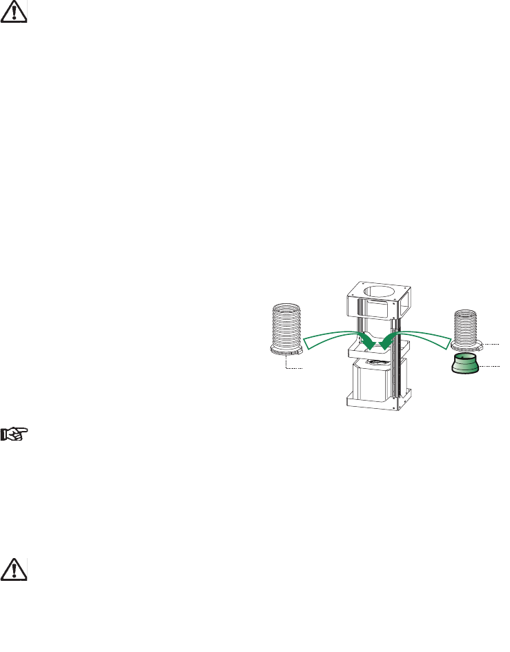
Recirculation Connection
Assemble the two halves of the round
recirculation extension duct 14.
Push fit the assembled extesion duct 14
on to Ø150mm ducting spigot on top of
the motor housing.
Push fit the recirculation spigot 15 onto
the other end of the extension duct 14.
Insert the extension ducts item 14.1 into
either side of the recirculation spigot 14
ensuring the connections are vertically
and horizontally aligned with the outlets
in the chimney.
Chimney Stack
The chimney consists of two sections. The lower
chimney measures 740mm (with the recirculation
grilles on either side) and the upper chimney
measures 215mm. The overall installed
measurement is min. 740-940mm max.
Fitting the Chimney
Position the upper chimney section 2.1 and
fix the chimney to the upper frame using two
Ø2.9x9.5mm screws 12c.
Slide the lower chimney section 2.2 up over
the upper chimney and fix the chimny to the
lower frame using two Ø2.9x9.5mm screws
12c.
When installed in the recirculation mode the
ducting outlet extension pieces 14.1 should
align with the rectangular holes in each side
of the chimney.
Position the recirculation grilles 8a and 8b so
the slats face in a forwards and upwards
direction.
Fitting the Hood Body 1
Before fixing the hood body to the frame:
Remove the grease filters from the hood
body.
Remove the activated charcoal filter.
Using the four M6x10 12f fix the hood body
1 to the frame 7.1b.
12f
8b
8a
12c
12c
14
15
14.1


