Operating Manual
Rotor
End
Gear
End
Spacer
Spacer
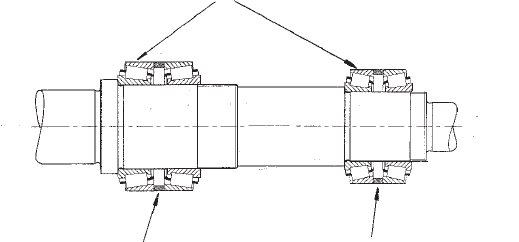
Note Direction of Tapers
Bearing Assembly
1. Remove rotorcase front cover, rotor and
rotorcase.
2. Remove product seals.
3. Remove the gearcase rear cover, timing
gears and drain lubricant.
4. Remove the gearcase front seal retainers
and seals.
5. The shaft assemblies can now be removed
through the front end of the gearbox, a
soft faced mallet may be used to tap them
out. The top chamber can now be
completely drained. Ensure that the
spacer located in the front bottom shaft
bearing housing is retained for refitting.
The DRM range of pumps utilise taper roller
bearings which are arranged in two sets of
double bearings front and back, assembled
with individual spacers. Refer to the exploded
diagrams at the rear of the manual.
10.6 Shaft Removal
10.7 Bearings - General
1. Load shaft into vice in a vertical position
and apply anti-seize compound to the
bearing diameters.
2. Working first on the front set of bearings,
use an induction heater or oil bath to heat
the front bearing cone to 110ºC. Pass the
bearing over the rear bearing diameter
and ensure a positive fit on the front
bearing diameter against the shaft
shoulder. The bearing taper should be
towards the gear end of the shaft.
10.9 Fitting Bearings to Shaft
To remove the bearings, undo the notched
bearing nut using a C- spanner, the bearing
assembly can now be dismantled. The bearing
cones are shrunk onto the shaft and will require
pressing off.
10.8 Bearings Removal
3. Locate outer shell of bearing onto the
cone just fitted.
4. Locate bearing spacer onto shell just fitted.
5. Locate rear bearing shell, of front set of
bearings, onto the spacer.
6. Heat rear bearing cone to 110ºC and fit to
bearing diameter. The taper should be
towards the rotor end of the shaft.
7. Allow bearings to cool.
8. Locate shaft in vice in horizontal position.
9. Apply Permabond grade 145 sealant or
equivalent to the shaft front lock nut thread
and screw front lock nut onto the shaft.
Whilst continuously rotating both bearings
and spacer, torque up the bearing lock nut
until the spacer cannot be moved radially
(off the shaft centre line) by finger pressure
alone, but can be moved with a light blow
of a hammer.
10. Repeat the above procedure for the rear
set of bearings, but in this case torque up
the lock nut until the spacer can be just
moved by finger pressure alone.
35
