PARTS REPLACEMENT
– 33 –
9
8
4
4
6
6
6
7
7
3
5
4
2
1
2
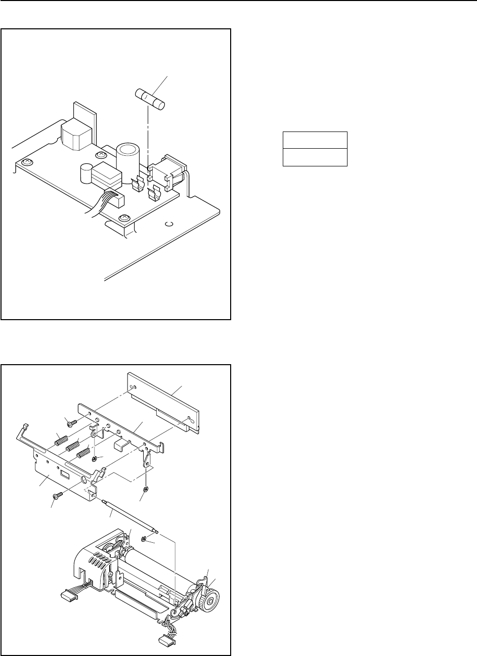
8. Thermal-head Unit
(1) Remove the printer mechanism. (See 3. above.)
(2) Be sure that the unit is in head-down state (that the
head-lift lever 1 is back).
(3) Press the two head-opening levers 2 and remove the
set cover 3 from the printer mechanism.
(4) Remove:
• Three stop rings 4
• Stay 5
• Three springs 6
• Two screws 7
• Head plate 8
• Thermal head 9
(5) Attach the replacement thermal head. as follows.
(a)Be sure that the unit is in head-open state.
(b)Hold the replacement head in position, and screw
the right end loosely into place with the one of the
screws 7.
(c)Set the unit into head-closed state.
(d)Fit the remaining screw 7 into the left side, and
tighten both of the screws to a torque of 5g-cm.
(6) Caution:
Keep hands clear of the head’s heat elements when
making the replacement.
Fuses (TSP200-24)
(1) Remove the main chassis unit from the lower casing
unit. (See 5. above.)
(2) Check the fuses in the power unit.
• Fuse F1 1
If fuse is blown, replace it with the fuse type
indicated below.
F1
5TT3A
If the replacement fuse also blows out, replace the
power unit or check the main logic board.
1


