


GBC 2064WF-1 Operation Manual
© 2009 General Binding Corporation an ACCO Brands CO. Page 14
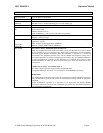
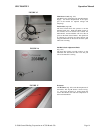
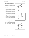
FIGURE 15
A
B
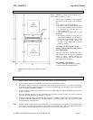
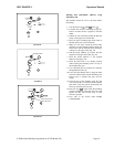
FIGURE 16
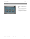
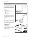
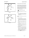
FIGURE 17
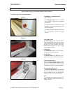
Main Power Cord: (Fig. 15A)
The Main Power Cord Plugs into the Main Power
Supply. See Power Requirements in the Specs
part of the manual for required Voltage and
Amperage.
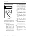
Foot Switch: (Fig.15B)
The Foot Switch allows the operator to run the
machine hands free. When the PICO System is
not blocked, the Foot Switch will activate the
Main Rollers, and the machine will run at the set
speed on the Main Control Panel. The Speed can
be adjusted by selecting the Speed button and
using the Main Dial to increase or decrease speed
while unit is running.
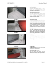
Pull Roll Clutch Adjustment Knob:
(Fig. 16A)
The Pull Roll Clutch provides tension on the
laminated film between the main rolls and pull
rolls as the material is cooling.
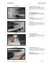
IR Sensor:
The IR Sensor (Fig. 16A) reads the temperature of
the Rollers. The Top IR Sensor is shown in Fig.
17. The Lower IR Sensor is located under the
Lower Heat Roller and reads the temperature of
the Lower Heat Roller