MN-28664 • Rev 2 (06/13) • ASC-4G Gas Convection Oven - Manual Control • 6
GAS SUPPLY & INSTALLATION
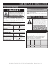
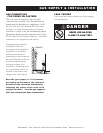
DANGER
Installation, air adjustment and/or
service work must be in accordance
with all local codes and must be
performed by a certifi ed service
technician qualifi ed to work on
gas appliances.
GAS REQUIREMENTS
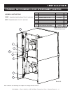
The gas inlet is located at the back of the oven.
Code requires the installation of a manual gas
shutoff valve to be installed in the gas line ahead
of the oven. This oven is also equipped with
fixed burner orifices determined by the elevation
specified as the initial installation location.
The oven is furnished with a regulator integral
to the operation of the gas solenoid valve
and may not require an additional external
regulator. To ensure safe and proper operation,
the gas pressure regulator installed in the oven
is required for use with both natural gas and
propane. If the connected pressure exceeds
14.0" W.C. (3.48 kPa), a step-down regulator
is required. A step-down regulator is not the
responsibility of the manufacturer.
Use an approved pipe sealant at all connections.
Do not use Teflon® tape. Gas supply connections
and pipe joint compound must be resistant to the
action of propane gases. Pipes must be clean, free
of obstructions and pipe joint compound.
GAS CONNECTION
In the U.S.A., installation must conform to local
codes or, in the absence of local codes, with the
current edition of the National Fuel Gas Code,
NFPA-54 and ANSI Z223.1-1980 (latest edition).
In Canada, installation must be in accordance
with local codes, CAN/CGA-B149.1,
Installation
for Natural Gas Burning Appliances and
Equipment (latest edition) or CAN/CGA-B149.2
Installation for Propane Burning Appliances
and Equipment (latest edition).
The inlet supply line must be properly sized
to accommodate all individual appliances
simultaneously used on the same line but
must never be smaller than 3/4" NPT.
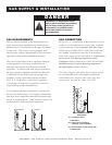
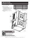
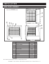
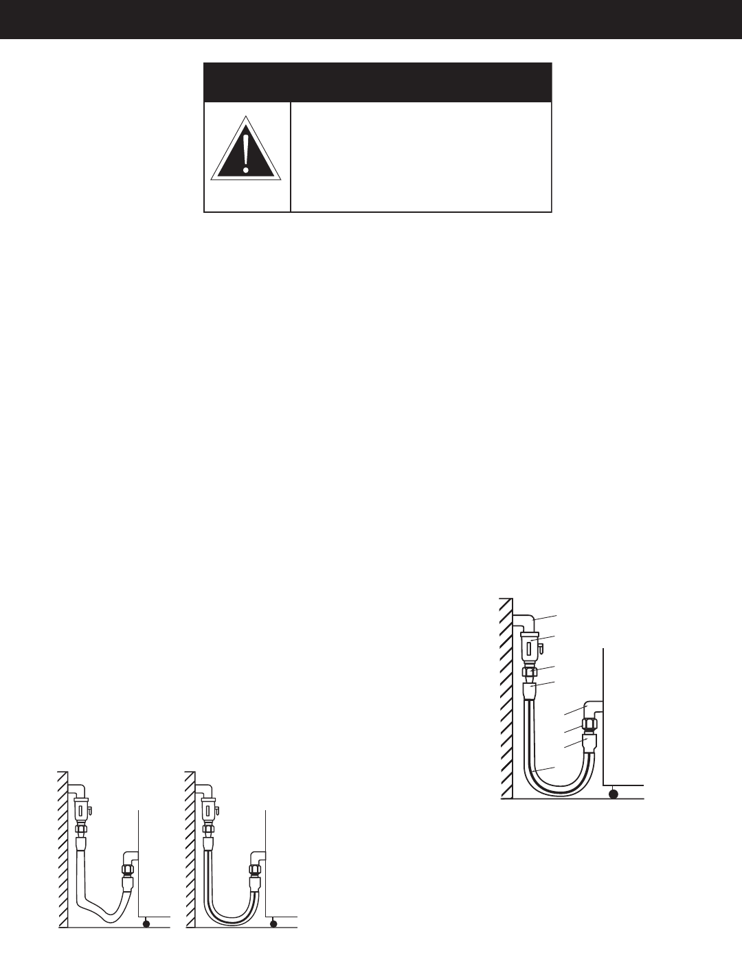
INCORRECT CORRECT
A
B
C
D
E
F
G
H
GAS INTAKE
A-G Installation elbow
B Ball Valve
C-D Three-piece union fi tting
(minimum 1 per installation)
E-F End connector for the fl exible tube
H Marking line


