


11
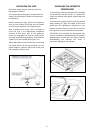
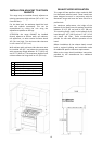
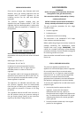
INSTALLINGTHEANTI‐TIPStabilityDEVICE
Theanti‐tipbracketshippe d withtherangemust
beproperlysecuredtotherearwallasshownin
thepicturebelow.
Theheightofthebracketfromthefloormustbe
determined after the range legs have been
adjusted to the desired height and
afterthe
rangehasbeenlevelled.
Measure the distance from the floor to the
bottomof theanti‐tip bracketreceptacleon the
backoftheappliance.
Position the twoanti‐tip bracketson thewall at
the desired height plus 1/8" (0.32 cm). The
bracketsmustbeplacedat
2”5/16(6,0cm)from
theside oftherange. Thedistan ce betweenthe
twobracketis31”1/4(79.3cm).
Securethebracketstothewallwithappropriate
hardware.
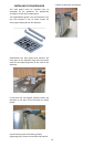
Slidetherangeagainstthewalluntilthebrackets
are fully inserted into their receptacles on the
backoftherange.
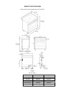
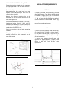
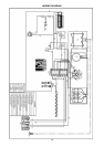
INSTALLATIONREQUIREMENTS
ELECTRICAL
A properly grounded and horizontally‐mounted
electrical receptacle Type NEMA 14‐50R should
beinstallednohigherthan3"(7.6cm)abovethe
floor, no less than 2” (5 cm) and no more than
11” (28 cm) from the left side (facing product);
refer to ELECTRICAL CONNECTION section pag.
13.
Checkalllocalcoderequirements.
GAS
Anagency‐approved,properly‐sizedmanualshut‐
off valve should be installed no higher than 3"
(7.6 cm) above the floor and no less than 2” (5
cm)andnomorethan8”(20.3cm)fromtheright
side(facingproduct).
To connect gas
between shut‐off valve and
regulator, use agency‐approved, properly sized
flexible or rigid pipe. Check all local code
requirements.