4.5 INSTALLING 8’’ DUCTS AND REGISTERS (CONT’D)
How to connect the 8’’ flexible duct to the registers and unit ports (cont’d)
• Using the colored sticker dot included, identify which duct it is (red dot for
stale airflow and blue dot for filtered airflow). Repeat the procedure for the
other register.
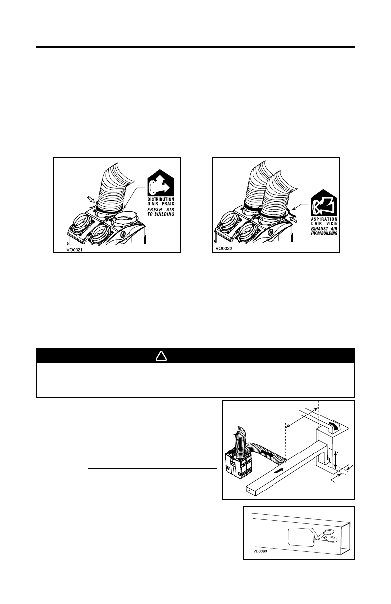
• Each port is identified on top of the unit (see illustrations below). Attach the
fresh air to building duct (the one with the blue dot) to its corresponding port,
using tie wrap (1). Then, attach the exhaust air from building duct (the one
with the red dot) to the other 8’’ port (2).
NOTE: Use a 8’’ insulated duct (not included) if the duct will have to go through a
non-tempered room (eg: in northern area, not heated attic in winter or attic
not cooled in southern area). Also, if you plan to stop the unit for more than
12 hours, we recommend to cover the duct with R12 insulation.
4.5.2 C
ENTRAL DRAW POINT (AS ILLUSTRATED IN SECTIONS 2.1.2 AND 2.3.2)
Stale air ductwork
Same as for Stand Alone System, described in point 4.5.1.
Fresh/Filtered air ductwork (Return side connection)
• Trace a 10 1/4’’ x 6 7/8’’(260 mm x175mm)
opening on the forced air unit return duct
at a minimum linear distance of 9’10” (3 m)
upstream (from forced air unit drop:
A+B+C).
NOTE: F
or Hepa 1000 and HF 1.0 units
only, the minimum linear
distance is 2’ (0.61 m) upstream
(A+B+C).
• Using a metal shear or a hammer and a flat
blade screwdriver, punch a hole into the
furnace/air handler return duct. Then, using
metal shear, cut out the rectangular hole.
12
WARNING
When performing duct connections, always use approved tools and
materials. Respect all corresponding laws and/or safety regulations. Please
refer to your local building code.
4. INSTALL THE UNIT (CONT’D)
VD0114
A
B
C
minimum
9’10” (3 m)
upstream
- 21 -


