5
ELECTRICAL REQUIREMENTS
CAUTION: The dispenser must be disconnected from the power source until specified in Electrical Hook-Up.
The LCA-2 and LCC-2 dispensers are supplied with a 120-volt / 15 Amp cord set and require a 2-wire, grounded,
individual branch circuit rated for 120 volts AC, 15 amp, single phase, 60Hz. The mating connector must be
a NEMA 5-15R.
The LCA-2C and LCC-2C dispensers are supplied with a 120-volt / 20 Amp cord set and require a 2-wire,
grounded, individual branch circuit rated for 120 volts AC, 20 amp, single phase, 60Hz. The mating connector
must be a NEMA 5-20R.
These dispensers can be Field Wired for 208 or 240 volt applications. This requires a 2 or 3-wire, grounded,
individual branch circuit rated for 208/240 volts AC, 30 amp, single phase, 60 Hz.
NOTE: The internal terminal block must be rewired for 208/240 applications, (see Optional Field Wiring
Diagram).
120V A.C.
120V A.C.
208 or
240V A.C.
HEATER RED
208 or
240V A.C.
120V A.C.
10A. FUSE - WHITE
HEATER RED
10A. FUSE - WHITE
10A. FUSE - BLACK
LIMIT SW. - BLACK
HEATER RED
10A. FUSE - WHITE
10A. FUSE - BLACK
LIMIT SW. - BLACK
10A. FUSE - BLACK
LIMIT SW. - BLACK
FIELD WIRING TERMINAL BLOCK DIAGRAM
34960.0000B 11/02 © 2002 BUNN-O-MATIC CORPORATION
For all 208 - 240 Volt Connections: Use No. 10 AWG Wires suitable for 90°C (194°F)
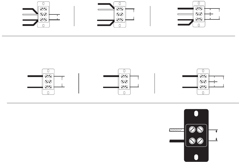
1. Unit shipped per Fig. 1, wired for 120V A.C./2-Wire.
2. For 208 - 240V A.C./2-Wire per Fig. 2: Move both the Red-Heater wire and the White-Fuse wire to the Top Red Terminal as shown.
3. For 120/208 - 240V A.C./3-Wire per Fig. 3: Move the Red Heater wire to the Top Red Terminal as shown.
Fig. 1 Fig. 2 Fig. 3
34766 062210
120V A.C.
120V A.C.
208 or
240V A.C.
RED
208 or
240V A.C.
120V A.C.
TO MASTER
ON/OFF
SWITCH
BLACK
RED
TO MASTER
ON/OFF
SWITCH
BLACK
RED
TO MASTER
ON/OFF
SWITCH
BLACK
FIELD WIRING TERMINAL BLOCK DIAGRAM
34960.0001A 01/07 © 2007 BUNN-O-MATIC CORPORATION
For all 208 - 240 Volt Connections: Use No. 10 AWG Wires suitable for 90°C (194°F)
1. Unit shipped per Fig. 1, wired for 120V A.C./2-Wire.
2. For 208 - 240V A.C./2-Wire per Fig. 2.
3. For 120/208 - 240V A.C./3-Wire per Fig. 3.
Fig. 1 Fig. 2
Fig. 3
FIELD WIRING TERMINAL BLOCK DIAGRAM
Models with Master ON/OFF Switch
FIELD WIRING TERMINAL BLOCK DIAGRAM
Models without Master ON/OFF Switch
CE REQUIREMENTS
• This appliance must be installed in locations where it can be overseen by trained personnel.
• For proper operation, this appliance must be installed where the temperature is between 5°C to 35°C.
• Appliance shall not be tilted more than 10° for safe operation.
• An electrician must provide electrical service as specied in conformance with all local and national codes.
• This appliance must not be cleaned by water jet.
• This appliance is not intended for use by persons (including children) with reduced physical, sensory or mental capabili-
ties, or lack of experience and knowledge, unless they have been given instructions concerning use of this appliance by
a person responsible for its safety.
• Children should be supervised to ensure they do not play with the appliance.
• If the power cord is ever damaged, it must be replaced by the manufacturer or authorized service personnel with a special
cord available from the manufacturer or its authorized service personnel in order to avoid a hazard.
• Machine must not be immersed for cleaning.
The LCR-2A dispenser is internally wired from the factory for 230 Volts
AC Single Phase 50/60 Hz. It requires a 2-wire, grounded, individual
branch circuit rated for 230 Volts AC.
L2 RED
L1 BLACK
200, 230 or
240V A.C.
230V A.C.


