4
INITIAL SET-UP
CAUTION: The dispenser is very heavy! Use care when lifting or moving it. Use at least two people to lift or
move the dispenser. Place the dispenser on a sturdy counter or shelf able to support at least 250 lbs. (113.4
kg). The FCD-4 is designed for indoor use only.
1. Set the dispenser on the counter where it will be used. The
FCD-4 requires a minimum of 4 inches (102 mm) of air
clearance at the rear and 8 inches (203 mm) of air clear-
ance above the dispenser. Minimal clearance is required
between the dispenser sides and the wall or another appli-
ance. For optimum performance,
do not let warm air from
surrounding machines blow on the FCD-4. Leave some
space so the dispenser can be moved for cleaning.
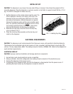
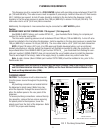
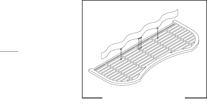
2. Assemble the cup stop in the third slot of the drip tray
cover as shown in Fig 1.
3. Place the cover/cup stop assembly on the drip tray and
install on the dispenser.
ELECTRICAL REQUIREMENTS
CAUTION: The dispenser must be disconnected from the power source until specified in
Electrical Hook-Up
.
The dispenser has an attached cord set and requires a 2-wire, grounded, individual branch circuit rated 120
volts ac, 15 amp, single phase, 60Hz. The mating connector must be a NEMA5-15R. (Refer to the dataplate for
exact electrical requirements.)
ELECTRICAL HOOK-UP
CAUTION: Improper electrical installation will damage electronic components.
1. An electrician must provide electrical service as specified.
2. Using a voltmeter, check the voltage and color coding of each conductor at the electrical source.
3. Connect the dispenser to the power source.
4. If plumbing is to be hooked up later, be sure the dispenser is disconnected from the power source. If
plumbing has been hooked up, the dispenser is ready for
Initial Fill
.
FIG 1 Installing Cup Stop
P2264.50
33496 011101


