


11
SERVICE (cont.)
Electronic Controls (cont.)
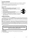
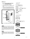
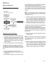
Liquid Level Control Test Procedure
1. Disconnect the dispenser from the power source.
2. Check the voltage across terminals 3 & 4 of the
electronic control assembly with a voltmeter. Con-
nect the dispenser to the power source. The indi-
cation must be 200 to 240 volts ac for 200 to 240
volt models.
3. Disconnect the dispenser from the power source.
If voltage was present as described, proceed to #4.
If voltage was not present as described, refer to
the Wiring Diagrams and check the dispenser wir-
ing harness.
4. Remove the pink wire from terminal 5 of the elec-
tronic control assembly.
5. Check the voltage across terminals 1 & 4 of the
electronic control assembly with a voltmeter. Con-
nect the dispenser to the power source. The indi-
cation must be 200 to 240 volts ac for 200 to 240
volt models after a delay of approximately 5 sec-
onds.
6. Disconnect the dispenser from the power source.
If voltage was present as described, the liquid level
control of the system is operating properly, proceed to
#7.
If voltage was not present as described, replace the
electronic control assembly and the temperature sen-
sor in the tank lid.
NOTE - Each electronic control assembly is calibrated
to a temperature sensor. Both components MUST be
replaced as a set.
7. Reconnect the pink wire to terminal 5 of the elec-
tronic control assembly.
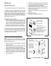
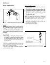
8. Loosen the compression fitting, remove the probe
from the tank lid, and inspect it for mineral depos-
its. Replace it if necessary. Keep the exposed ends
of the probe away from any metal surface of the
dispenser.
9. Check the voltage across the terminals 1 & 4 of the
electronic control assembly with a voltmeter. Con-
nect the dispenser to the power source. The indi-
cation must be 200 to 240 volts ac for 200 to 240
volt models after a delay of approximately 5 sec-
onds.
10. Touch the screw head end of the probe to the dis-
penser housing. The indication must be 0.
11. Move the probe away from the dispenser housing.
The indication must again be 200 to 240 volts ac
for 200 to 240 volt models after a delay of approxi-
mately 5 seconds.
12. Disconnect the dispenser from the power source.
If voltage was present as described, reinstall the probe,
the sensing function of the system is operating prop-
erly.
If voltage was not present as described, check the pink
probe wire and the green ground wire for continuity
and/or replace the probe.
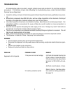
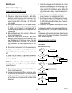
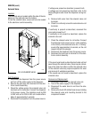
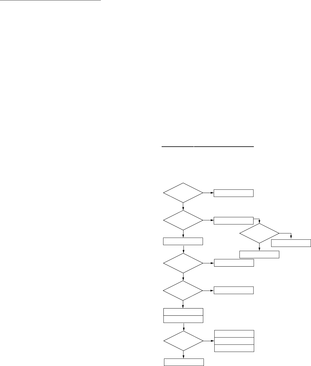
Temperature control Flow Charts
Limit Thermostat OK
?
Heater Light On
Constantly
?
Measure Voltage
At Tank Heater
No
No
Ye s
Ye s
Ye s
No
No
H10X THERMOSTAT
PROBLEM: Water Not Hot Enough
Replace Limit Thermostat
Voltage Present
?
Voltage Present
?
Ye s
Measure Voltage
At Tank Heater
Replace Tank Heater
Replace Control Assembly
Replace Triac
Reinstall Original
Control Assembly
Check For Split Tank Heater
Recheck Water Temperature
Replace Steam Sensor
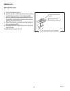
Heater Light On
Constantly
?
Replace Control Assembly
Ye s
No
Recheck Water Temperature
Jumper JP1
In Boil Position
?
Ye s
No
Reposition Jumper
10889 091599