


13
SERVICE (cont.)
Electronic Controls (cont.)
11. Disconnect the dispenser from the power source.
If voltage was present as described, return the new
triac assembly to Bunn-O-Matic for credit. The tem-
perature control of the system is operating properly. If
voltage was not present as described, reinstall your
existing electronic control assembly and temperature
sensor, and proceed to #12
12. Replace the triac assembly.
13. Check the voltage across the tank heater terminals
with a voltmeter. Connect the dispenser to the
power source. The indication must be 200 to 240
volts ac for 200 to 240 volt models while the red
indicator on the circuit board is on or blinking.
14. Disconnect the dispenser from the power source.
If voltage was present as described, the temperature
control of the system is operating properly. Return the
new electronic control assembly and temperature sen-
sor to Bunn-O-matic for credit.
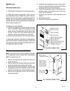
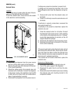
Electronic Control Removal and Replacement
NOTE - Each electronic control assembly is calibrated
to a temperature sensor probe. Both components
MUST be replaced as a set.
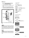
1. Remove all wires from the electronic control as-
sembly terminals.
2. Remove the two 8-32 screws holding the electronic
control assembly to the component bracket.
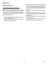
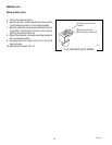
3. Disconnect the temperature sensor, overflow tube
temperature sensor, and indicator wires from the
left side of the electronic control assembly board.
4. Remove the temperature sensor from the grom-
met in the tank lid.
5. Install the new temperature sensor into the grom-
met on the tank lid. Route the wires to the location
of the new electronic control assembly.
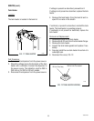
6. Attach the temperature sensor, overflow tube tem-
perature sensor, and indicator wires to the elec-
tronic control assembly.
7. Fasten the new electronic control assembly to its
bracket.
8. Reconnect the wires.
9. Review the initial set-up procedures.
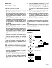
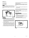
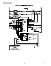
BLU to Triac Assy
TAN to Triac Assy
BLU to Triac Assy
TAN to Triac Assy
PNK to Liquid Level Probe
RED to Terminal block
RED to Solenoid
BLK to Overflow Safety Switch
GRN to Chassis Ground
WHI/BLU to Solenoid
P1992
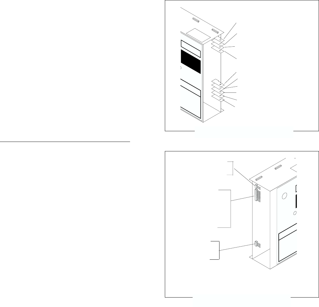
FIG. 2 WIRING CONNECTIONS
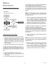
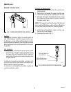
WHI & WHI to
Temperature Sensor
PNK & GRY to
Heater Indicator
Refill Indicator
Power Indicator
Ready Indicator
GRY & GRY
to Thermistor
P1992
FIG. 3 WIRING CONNECTIONS
P1
P2
P101
10889 091599