


12
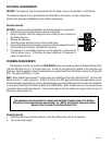
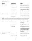
SERVICE (cont.)
Electronic Controls (cont.)
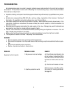
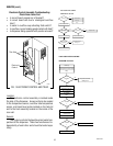
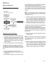
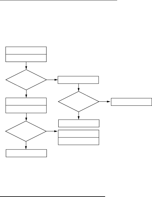
Temperature Control Flow Charts (cont.)
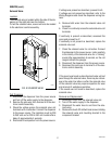
Still Boiling
?
Heater Light On While
Boiling
?
Retry
Drain cup
Retry
Disconnect Blue Wire From
Control Board Pin 7
No
Ye s
Ye s
Ye s
No
No
H10X THERMOSTAT
PROBLEM: Boils Excessively - Fills Cup
Still Boiling
?
Replace Steam Sensor
Replace Triac Assembly
Check For Split
Tank Heater
Replace Control Assembly
Finished
Replace Control Assembly
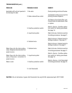
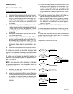
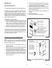
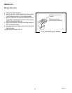
Temperature Control Test Procedure
1. Disconnect the dispenser from the power source.
2. Check the voltage across terminals 3 & 4 of the
electronic control circuit board with a voltmeter.
Connect the dispenser to the power source. The
indication must be 200 to 240 volts ac for 200 to
240 volt models.
3. Disconnect the dispenser from the power source.
If voltage was present as described, proceed to #4.
If voltage was not present as described, refer to the
Wiring Diagram and check the dispenser wiring har-
ness.
4. Connect the dispenser to the power source .
5. Observe the red indicator on the electronic control
circuit board.
6. Disconnect the dispenser from the power source.
If the indicator was on or blinking, the temperature
sensor is operating properly, proceed to #7.
If the indicator was off, check the sensor connection
on the electronic control circuit board and/or replace
the temperature sensor and the electronic control as-
sembly.
NOTE - Each temperature sensor is calibrated to an
electronic control assembly. Both components MUST
be replaced as a set.
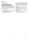
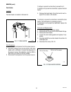
7. Check the voltage across the tank heater terminals
with a voltmeter. Connect the dispenser to the
power source. The indication must be 200 to 240
volts ac for 200 to 240 volt models while the red
indicator on the circuit board is on or blinking.
8. Disconnect the dispenser from the power source.
If voltage was present as described, the temperature
control of the system is operating properly.
If voltage was not present as described, contact Bunn-
O-Matic to order an electronic control assembly tem-
perature sensor, and triac assembly for evaluation and
proceed to #9.
9. Replace the electronic control assembly and tem-
perature sensor.
NOTE - Each electronic control assembly is calibrated
to a temperature sensor. Both components MUST be
replaced as a set.
10. Check the voltage across the tank heater terminals
with a voltmeter. Connect the dispenser to the
power source. The indication must be 200 to 240
volts ac for 200 to 240 volt models while the red
indicator on the circuit board is on or blinking.
10889 091599