15
SERVICE (cont.)
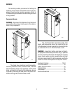
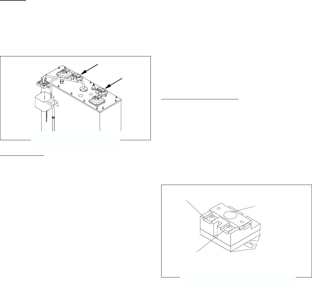
Limit Thermostat
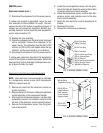
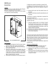
P1993
FIG. 5 LIMIT THERMOSTAT
Test Procedure:
1. Disconnect the dispenser from the power source.
2. There are two black wires on the limit thermostat
terminals. One comes from the terminal block. The
other goes directly to the tank heater terminal. Re-
move the black wire at the limit thermostat coming
from the terminal block.
3. Check the voltage across the black wire removed
from the limit thermostat and the red wire of the
terminal block with a voltmeter. Connect the dis-
penser to the power source. The indication must
be 200 to 240 volts ac for 200 to 240 volt models.
4. Disconnect the dispenser from the power source.
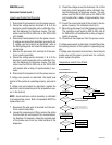
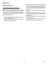
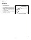
Reset
BLK to Terminal Block
BLK to Tank Heater
P1776
FIG. 6 LIMIT THERMOSTAT WIRING
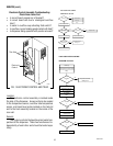
Limit Thermostat
Location:
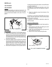
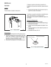
The limit thermostats are located on the tank lid. To
test the limit thermostats, access will also be needed
to the terminal block located on the side of the dis-
penser.
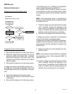
If voltage was present as described, reconnect the black
wire and proceed to #5.
If voltage was not present as described, refer to the
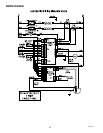
Wiring Diagrams and check the dispenser wiring har-
ness.
5. Check for continuity across the terminals of the
limit thermostat.
If continuity is not present as described, the circuit is
broken. Press the reset button of the limit thermostat
and recheck for continuity.
If continuity is not present as described, replace the
limit thermostat.
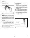
Removal and Replacement:
1. Remove both wires from the limit thermostat ter-
minals.
2. Remove the two #10-32 nuts attaching the limit
thermostat to the top of the tank.
3. Install the new limit thermostat and secure into
place with two #10-32 nuts.
4. Refer to FIG. 6 when reconnecting the wires.
10889 091599


