


42
12
11
9
8
7
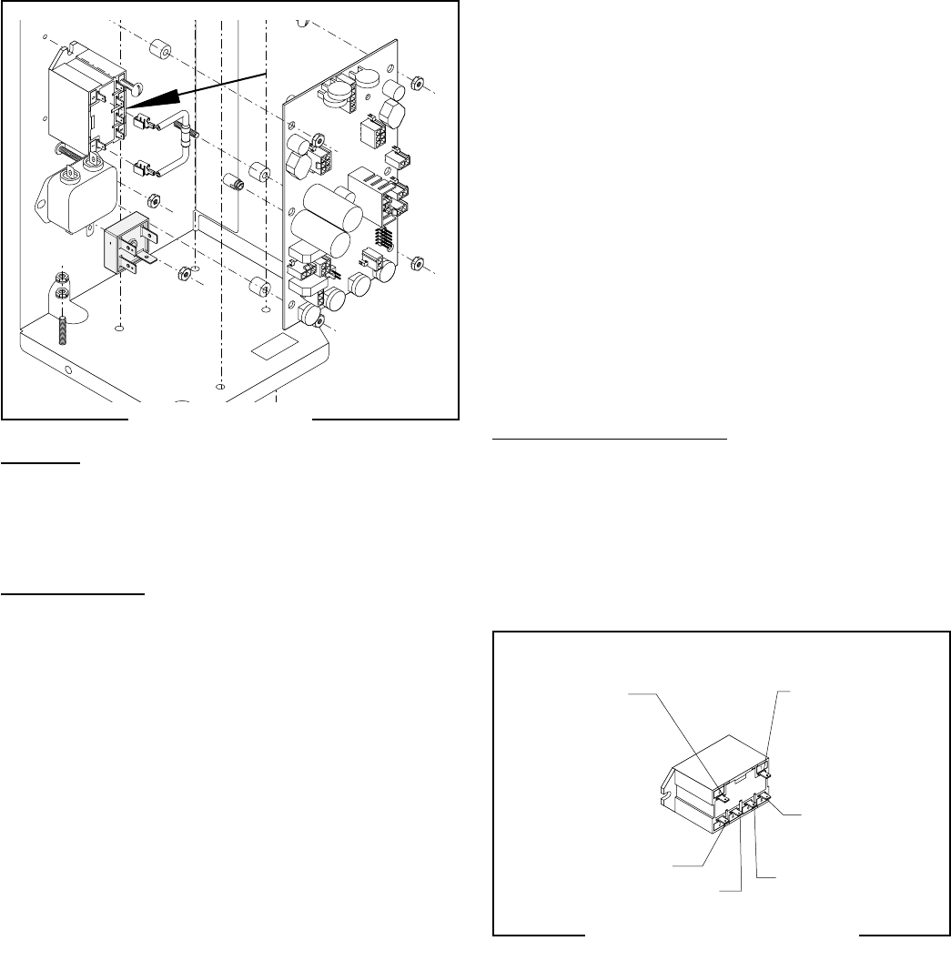
SERVICE (CONT.)
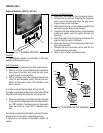
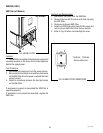
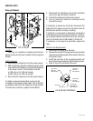
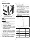
Relay (all Models)
FIG. 57 RELAY
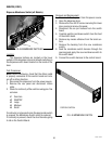
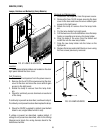
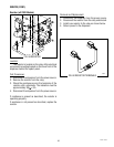
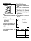
4. Disconnect the blue/black wire and the red/black
wires from relay terminals #4 and #6.
5. Connect the dispenser to the power source.
6. Turn on power and check for continuity across
terminals on relay.
If continuity is present as described, disconnect the
dispenser from power source and reconnect wires to
terminals #4 and #6, the relay is working.
If continuity is not present as described, do the same
continuity test across terminals #2 and #8. If continu-
ity is present between terminals #2 and #8, reconnect
wires to terminals #4 and #6 instead of #2 and #8.
If continuity is not present as described, replace the
relay.
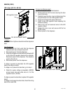
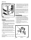
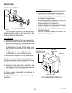
Removal and Replacement:
1. Disconnect the wires from the relay.
2. Remove the two #8-32 locking screws securing the
relay and mounting bracket to the chassis. Remove
and discard relay.
3. Install the new relay to the mounting bracket and
then on the chassis using two #8-32 locking screws.
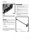
4. Refer to Fig. 58 to reconnect the wires.
Location:
The relay (or contactor) is located inside the dis-
penser chassis on the lower outside of the component
bracket.
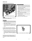
Test Procedures:
1. Disconnect the dispenser from the power source.
2. With a voltmeter, check the voltage across the white
wire and the white/black wire. Connect the dispenser
to the power source. The indication must be:
a) 120 volts ac for 120 volt models.
b) 230 volts ac for 230 volt models.
3. Disconnect the dispenser from the power source.
If voltage is present as described, proceed to #4.
If voltage is not present as described, refer to the Wir-
ing Diagram and check the dispenser wiring harness.
If harness has continuity, replace Control Board.
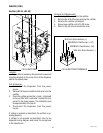
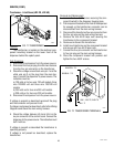
FIG. 58 RELAY TERMINALS
Terminal #0
WHI from
Main Harness
Terminal #6
WHI/ORN from
Main Harness
Terminal #8
BLK from
Main Harness
Terminal #1
BLK from
Main Harness
Terminal #2
Terminal #4
49179 110613