


Page 18
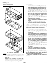
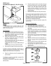
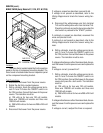
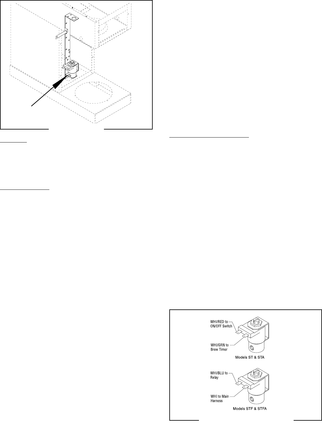
SOLENOID VALVE (Models ST, STA, STF & STFA)
Location:
The solenoid valve is located inside the front
inspection panel on the center lower part of the com-
ponent mounting bracket.
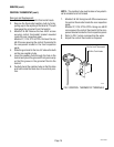
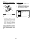
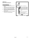
Test Procedures:
1. Disconnect the brewer from the power source.
2. Disconnect the wires (FIG. 9) from the solenoid
valve. With the "ON/OFF" switch in the "ON" upper
position press the start switch.
3. Check the voltage across the two wires with a
voltmeter. Connect the brewer to the power
source. The indication must be:
a) 120 volts ac for two wire 120 volt models and
three wire 120/240 volt models.
b) 200 to 240 volts ac for two wire 200 or 240 volt
models.
c) 100 volts ac for two wire 100 volt models.
4. Disconnect the brewer from the power source.
If voltage is present as described, proceed to #5. If
voltage is not present as described, refer to
Wiring
Diagrams
and check brewer wiring harness.
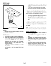
5. Check for continuity across the solenoid valve
coil terminals.
If continuity is present as described, reconnect the
wires (FIG. 9) to the solenoid.
If continuity is not present as described, replace the
solenoid valve.
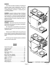
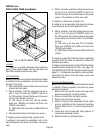
SERVICE (cont.)
P1587
P1588
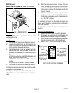
6. Check the solenoid valve for coil action. Connect
the brewer to the power source. With "ON/OFF"
switch in the "ON" upper position press start
switch and listen carefully in the vicinity of the
solenoid valve for a" clicking" sound as the coil
magnet attracts.
7. Disconnect the brewer from the power source.
If the sound is heard as described and water will not
pass through the solenoid valve, there may be a
blockage in the water line before the solenoid valve or,
the solenoid valve may require inspection for wear,
and removal of waterborne particles.
If the sound is not heard as described, replace the
solenoid valve.
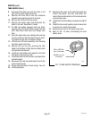
Removal and Replacement:
1. Remove the wires from the solenoid valve.
2. Turn-off the water supply to the brewer.
3. Disconnect the water lines to and from the sole-
noid valve.
4. Remove the two #8-32 screws securing the so-
lenoid mounting bracket to the component
bracket. Remove solenoid bracket and solenoid
valve as an assembly.
5. Remove the two #10-32 screws and lockwashers
securing the solenoid valve to the solenoid
bracket.
6. Using two #10-32 screws and lockwashers in-
stall new solenoid valve on solenoid mounting
bracket.
7. Using two #8-32 screws install solenoid valve
and bracket to the component bracket.
8. Securely fasten the water lines to and from the
solenoid valve.
9. Refer to FIG. 9 when reconnecting the wires.
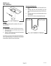
FIG. 8 SOLENOID
FIG. 9 SOLENOID TERMINALS
29251 052500