


Page 27
P1599
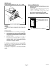
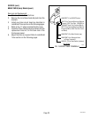
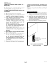
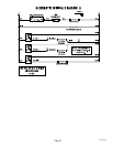
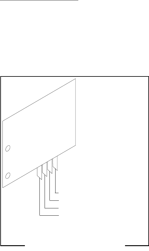
FIG. 19 LIQUID LEVEL CONTROL
BOARD TERMINALS
BLU to Relay 2
WHI/RED to Relay 5 and Timer TL1
WHI to Timer TL2
PNK to Probe
29251 052500
SERVICE (cont.)
LIQUID LEVEL CONTROL BOARD (Models STF &
STFA)(Cont,)
If voltage is present as described, the level control
board is operating properly, proceed to #11.
If voltage is not present as described, replace the level
control board.
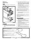
11. Reconnect the pink wire to terminal 4.
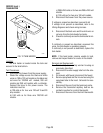
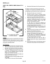
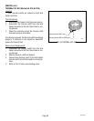
12. Gently pull the probe out of the tank lid and
inspect for corrosion. Replace it if necessary.
13. Place the probe so that neither end is in contact
with any metal surface of the brewer.
14. Check the voltage across terminals 1 & 3 with a
voltmeter. Connect the brewer to the power
source. Turn the "ON/OFF" switch to the "ON"
position. The indication must be:
a.) 120 volts ac for three wire 120/208 volt mod-
els and three wire 120/240 volt models after a
delay of approximately 5 seconds.
b.) 200 to 240 volts ac for two wire 200 or 240
volt models after a delay of approximately 5
seconds.
15. Move the probe's flat end to the brewer housing.
The indication must be 0.
16. Move the probe's flat end away from the brewer
housing. The indication should again be:
a.) 120 volts ac for three wire 120/208 volt
models and three wire 120/240 volt models.
b.) 200 to 240 volts ac for two wire 200 or 240
volt models.
17. Disconnect the brewer from the power source.
If voltage is present as described, reinstall the probe,
the level control board and level probe are operating
properly.
If voltage is not present as described, check the pink
probe wire.
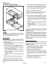
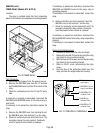
Removal and Replacement:
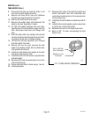
1. Remove all wires from the level control board.
2. Remove two #8-32 screws and lockwashers
holding level control board to component bracket.
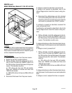
3. Install the new level control board to the
component bracket. Make certain that the
lockwashers are between the level control board
and the component bracket.
4. Refer to FIG. 19 when reconnecting the wires.