


Page 24
J
2
S
E
T
L
O
C
K
L
O
C
K
S
E
T
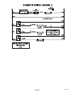
TL1
TL2
TL3
TL4
TL5
J1
SERVICE (cont.)
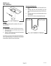
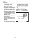
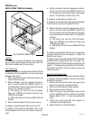
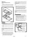
DIGITAL BREW TIMER (Late Models)
P2181
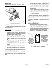
FIG. 16 DIGITAL BREW TIMER
29251 011501
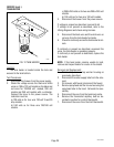
Location:
The timer is located inside the front inspection
panel. Some earlier models, with the new timer will
have them located inside the rear panel.
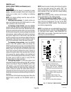
Test Procedures:
NOTE: Do not remove or install wires while timer board
is installed. Pressure applied to one side may cause
damage to the board.
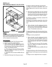
1. Disconnect the brewer from the power source and
remove the front panel.
2. With a voltmeter, check the voltage across termi-
nals TL1 and TL2 when the "ON/OFF" switch is in
the "ON" position. Connect the brewer to the power
source. The indication must be:
a.) 120 volts ac for two wire 120 volt models,
three wire 120/208 volt models and three wire
120/240 volt models.
b.) 200 to 240 volts ac for two wire 200 or 240 volt
models.
3. Disconnect the brewer from the power source.
If voltage is present as described, proceed to #4.
If voltage is not present as described, refer to the
Wiring Diagrams
and check the brewer wiring har-
ness.
4. With a voltmeter, check the voltage across termi-
nals TL1 and TL4 when the "ON/OFF" switch is in
the "ON" position. Connect the brewer to the power
source. The indication must be zero volts.
If voltage is as described, proceed to #5.
If voltage is not as described, disconnect the brewer
from the power source and replace the timer.
5. With a voltmeter, check the voltage across termi-
nals TL1 and TL4 when the "ON/OFF" switch is in
the "ON" position. Connect the brewer to the power
source and press the start switch. The indication
must be:
a.) 120 volts ac for two wire 120 volt models,
three wire 120/208 volt models and three wire
120/240 volt models.
b.) 200 to 240 volts ac for two wire 200 or 240 volt
models.
If voltage is as described, the brew timer is operating
properly. Reset the timer as required, to obtain the
desired brew volume.
If voltage is not as described, test the START switch for
operation before replacing the timer (see page 19).
Test ON/OFF Switch if START Switch is functional (see
page 17). If voltage is as described for both switches,
disconnect the brewer from the power source and
replace the timer.
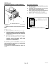
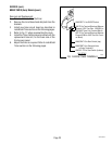
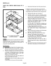
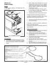
Removal and Replacement:
NOTE: Do not remove or install wires while timer board
is installed. Pressure applied to one side may cause
damage to the board.
1. Remove the two #6-32 screws securing circuit
board to component mounting bracket.
2. Remove circuit board and nylon spacers.
3. Remove all wires from the timer.
4. Attach all wires to the replacement timer board
prior to installation to the component mounting
bracket. Refer to FIG. 17 when reconnecting the
wires.
5. Install new circuit board with nylon spacers to
component mounting bracket.
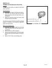
6. Adjust the timer as described below.