


Page 29
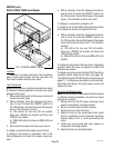
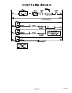
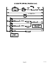
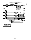
3. Check voltage across the WHI wire from the
terminal block and the wire from the "ON/OFF"
switch to the warmer element with a voltmeter
with the "ON/OFF" switch in the "ON" position.
The indication must be:
a) 120 volts ac for two wire 120 volt versions.
b) 120 volts ac for three wire 120/208 volt
versions or 120/240 volt versions.
4. Disconnect the brewer from the power source.
If voltage is present as described, proceed to #5.
If voltage is not present as described, refer to wiring
diagrams and check brewer wiring harness.
5. Check the continuity across the two terminals on
the warmer element.
If continuity is present as described, reconnect the
wires on the warmer element.
If continuity is not present as described, replace the
warmer element.
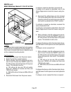
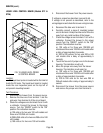
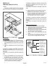
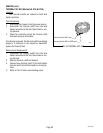
Removal and Replacement:
1. Remove the three #4-40 screws securing the
warmer assembly to the brewer.
2. Lift the warmer assembly from the brewer.
3. Disconnect the two wires from the warmer ele-
ment terminals.
4. Remove the two #8-32 nuts securing the warmer
element to the warmer plate.
5. Securely install new warmer element.
6. Reconnect the two wires to warmer element
terminals.
7. Securely install warmer assembly on the brewer.
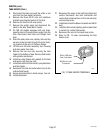
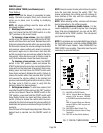
8. Refer to FIG. 23 when reconnecting the wires.
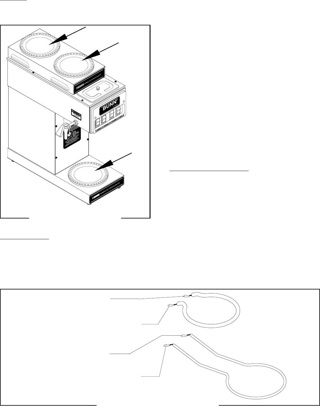
P1601
P1602
FIG. 22 WARMER ELEMENTS
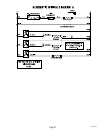
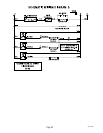
FIG. 23 WARMER ELEMENT TERMINALS
BRN/BLK Wire to Top Front Warmer Switch
BLU/BLK Wire to Top Rear Warmer Switch
WHI Wire to Terminal Block (White Insert on 120/208V or
120/240V Models) or
RED Wire to Terminal Block (Red Insert on 200V or 240V
Models)
WHI/VIO Wire to Lower Warmer/ON Switch
WHI Wire to Terminal Block (White Insert on 120/208V or
120/240V Models) or
RED Wire to Terminal Block (Red Insert on 200V or 240V
Models)
29251 052500
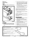
SERVICE (cont.)
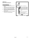
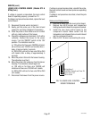
WARMER ELEMENTS
Location:
The warmer elements are located under the
warmer plates.
Test Procedures:
1. Disconnect the brewer from the power source.
2. Use the WHI wire to the terminal block and the
wire from the warmer element to the "ON/OFF"
switch.