


Page 25
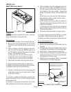
Removal and Replacement:
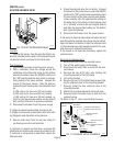
1. Remove the wires from the switch terminals.
2. Compress the clips inside the hood and gently
push the switch through the opening.
3. Push the new switch into the opening and spread
the clips to hold the switch captive in the hood.
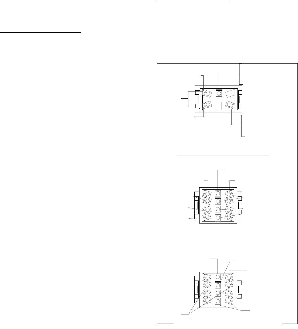
4. Refer to FIG. 17 when reconnecting the wires.
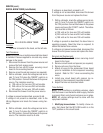
SERVICE (cont.)
ON/OFF SWITCH (SELECTOR SWITCH -
OPTIONAL)(CONT.)
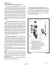
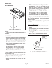
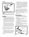
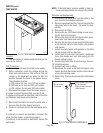
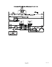
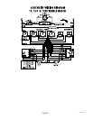
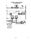
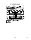
FIG.17 ON/OFF SWITCH TERMINALS
P1282
10225 031804
SWEET/UNSWEET
BREWERS W/HALF BATCH OPTION
BREWERS W/OUT HALF BATCH OPTION
BLK to Power Cord (100V &
120V Models
BLK to Power Connector
(240V Models)
WHI/VIO to Dilution
Timer
WHI/VIO
WHI/VIO to Brew
Timer TL1
WHI to Dilution Timer TL2
(100V & 120V Models)
RED to Dilution Timer (240V
Models)
BLK to Power Connector
WHI/VIO to Dilution Timer TL1
PNK to Brew Timer
PNK to Dilution Timer (Delay)
PNK to Dilution Timer
(Dilution)
WHI/VIO to Brew Timer
TL1
GRY to Brew Timer
GRY to Dilution
Timer (Delay)
GRY to Dilution
Timer (Dilution)
WHI
WHI/VIO
BRN/WHI to Sweetener
Solenoid
BLK to Power Connector
WHI/BLU to Dilution
Solenoid
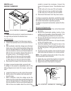
Brewers W/Sweetener Option:
1. Disconnect the brewer from the power source.
2. With a voltmeter, check the voltage across the
black wire and white wire on the selector switch.
3. Connect the brewer to the power source. The in-
dication must be:
a) 120 volts ac for two wire 120 volt models.
b) 240 volts ac for two wire 240 volt models.
c) 100 volts ac for two wire 100 volt models.
4. Disconnect the brewer from the power source.
If voltage is present as described, proceed to #5.
If voltage is not present as described, refer to the
Wir-
ing Diagrams
and check the wiring harness.
5. Disconnect the black and white wires from the
center terminals.
6. Disconnect the brown/white and white/violet wires
from the right side terminals.
7. Check for continuity across the center and right
terminals in rows one through four when the
switch is in the "SWEET” position.
If continuity is present as described, replace the wires
on the right side and proceed to #8.
If continuity is not present as described, replace the
switch.
8. Disconnect the white/violet wires on the left side
terminal.
9. Check for continuity across the center and left side
terminals in rows one through four when the
switch is in the "UNSWEET” position.
If continuity is present as described, replace the wires
the switch is operating properly.
If continuity is not present as described, replace the
switch.