


Page 14
SERVICE
This section provides procedures for testing and
replacing various major components used in this
brewer should service become necessary. Refer to
Troubleshooting
for assistance in determining the
cause of any problem.
WARNING - Inspection, testing, and repair of electri-
cal equipment should be performed only by qualified
service personnel. The brewer should be disconnected
from the power source when servicing, except when
electrical tests are required and the test procedure spe-
cifically states to plug-in the brewer.
COMPONENT ACCESS
WARNING - Disconnect the brewer from the power
source before the removal of any panel or the replace-
ment of any component.
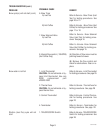
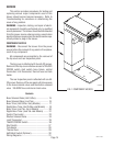
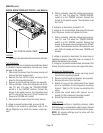
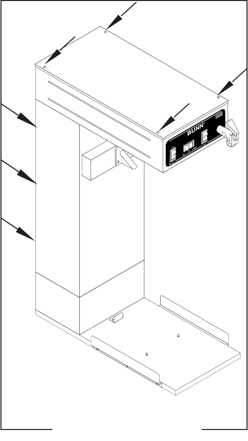
All components are accessible by the removal of
the top cover and rear inspection panel.
The top cover is attached with four #6-32 screws.
Removal of the top cover will allow access to TEA/OFF/
COFFEE switch, start switch, brew timers, control
thermostat, limit thermostat, thermal fuse and tank
heater.
The rear inspection panel is attached with six #8-
32 screws. Remove of the rear panel will allow access
to the brew solenoid valves and the dilution solenoid
valve .195 GPM flow control and check valve.
Contents
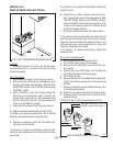
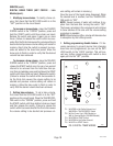
Brew Solenoid Valve (Hot Coffee) ....................... 15
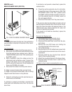
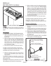
Brew Solenoid Valve (Iced Tea) .......................... 16
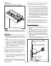
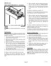
Brew Timer (Hot Coffee- Early Models) .............. 17
Digital Brew Timer (Hot Coffee-Late Models) ..... 18
Brew Timer (Iced Tea - Early Models) ................. 20
Digital Brew Timer (Iced Tea-Late Models) ......... 21
Control Thermostat............................................. 23
Dilution Solenoid Valve ....................................... 24
Limit Thermostat ................................................ 25
TEA/OFF/COFFEE Switch ..................................... 26
Start Switch ........................................................27
Tank Heater......................................................... 28
Thermal Fuse ...................................................... 29
Half Batch Switch (Optional)............................... 30
Wiring Diagrams................................................. 31
FIG. 1 COMPONENT ACCESS
P1959.60
10510 071000