


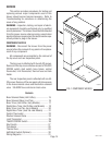
Page 20
Location:
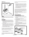
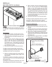
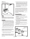
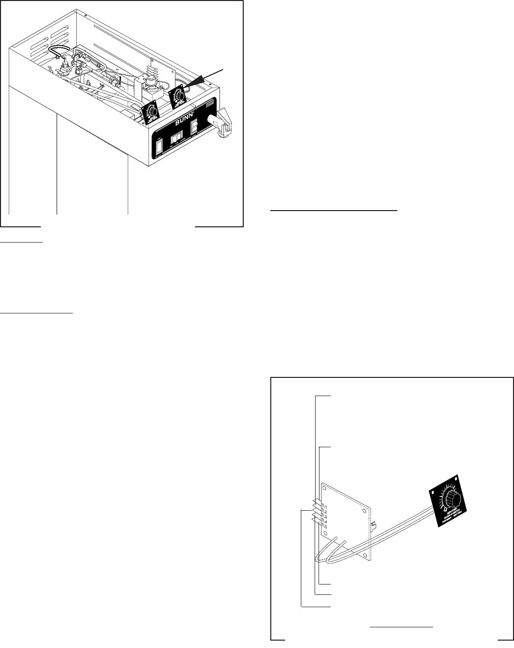
The iced tea brew timer is located in the hood on
the right side. It consists of the dial plate and circuit
board.
Test Procedure:
1. Disconnect the brewer from the power source.
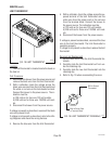
2. Remove the wires from terminals TL3, TL4, & TL5
of the iced tea timer and rotate the dial fully coun-
terclockwise.
2. With a voltmeter, check the voltage across termi-
nals TL1 and TL2 when the TEA/OFF/COFFEE
switch is in the “TEA” position. Connect the brewer
to the power source. The indication must be 120
volts ac for two wire 120 volt models and three
wire 120/208 volt models.
3. Disconnect the brewer from the power source.
If voltage is present as described, proceed to #4.
If voltage is not present as described, refer to the Wir-
ing Diagram and check the wiring harness.
4. Check for continuity across the orange and yel-
low wires when the START switch is held in the
lower position.
If continuity is present as described, reconnect the
wires to terminals TL3, TL4, & TL5 of the timer board
and proceed to #5.
If continuity is not present as described, refer to the
Wiring Diagrams
and check the wiring harness.
5. With a voltmeter, check the voltage across termi-
nals TL1 and TL4 when the TEA/OFF/COFFEE
switch is in the “TEA” position and the START
switch is momentarily placed in the lower posi-
tion. Connect the brewer to the power source. The
indication must be 120 volts ac for two wire 120
volt models and three wire 120/208 volt models
for approximately twenty seconds and then return
to its previous indication.
6. Disconnect the brewer from the power source.
If voltage is present as described, the timer is operat-
ing properly. Adjust the timer dial as required.
If voltage is not present as described, replace the timer.
Removal and Replacement:
1. Remove all wires from the iced tea brew timer.
2. Remove the circuit board and dial plate from the
brackets.
3. Install the new timer circuit board as described in
Late Model Timer
section on the following pages.
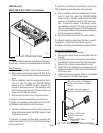
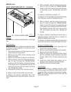
4. Refer to Fig. 13 when reconnecting the wires.
5. Install the Timer Setting decal, provided with the
replacement timer kit, to the rear of the schematic
on the top cover.
5. Adjust the timer as required. Refer to
Late Model
Timer
section on the following pages.
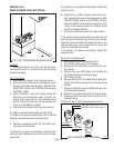
FIG. 11 ICED TEA BREW TIMER TERMINALS
P1962
FIG. 10 ICED TEA BREW TIMER
P1961.50
SERVICE (cont.)
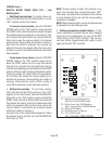
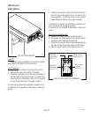
BREW TIMER (ICED TEA - Early Models)
WHI to Power Cord (120V Models)
or WHI to Terminal Block (120/208V
Models)
WHI/VIO to Iced Tea Solenoid
WHI/VIO to TEA/OFF/COFFEE Switch
YEL to START Switch
WHI/BLU to Iced Tea Solenoid
ORN to START Switch
EARLY MODELS
10510 071000