


Page 28
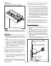
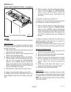
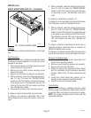
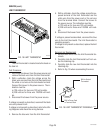
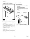
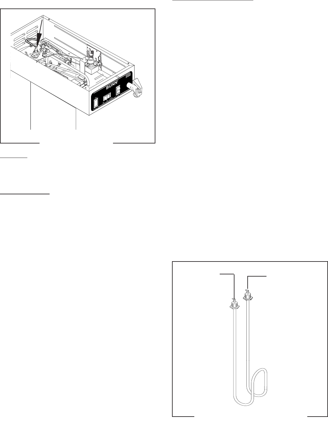
FIG. 24 TANK HEATER
Location:
The tank heater is located inside the tank and se-
cured to the tank lid.
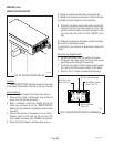
Test Procedures:
1. Disconnect the brewer from the power supply.
2. With a voltmeter, check the voltage across the
black and white wires on 120 volt models or the
black and red wires for 120/208 volt models. Con-
nect the brew to the power source. The indication
must be:
a) 120 volts ac for two wire 120 volt models .
b) 208 volts ac for three wire 120/208 volt mod-
els.
3. Disconnect the brewer from the power source.
If voltage is present as described, proceed to #4
If voltage is not present as described, refer to the
Wir-
ing Diagrams
and check wiring harness.
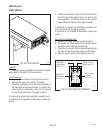
4. Disconnect the black wire and the white wire or
red wire from the tank heater terminals.
5. Check for continuity across the tank heater termi-
nals.
If continuity is present as described, reconnect the
wires, the tank heater is operating properly.
If continuity is not present as described, replace the
tank heater.
NOTE- If the tank heater remains unable to heat, re-
move and inspect heater for cracks in the sheath.
P2198.50
SERVICE (cont.)
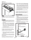
TANK HEATER
Removal and Replacement:
1. Disconnect the black wire and the white or red
wire from the tank heater terminals.
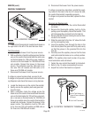
2. Remove sprayhead and the hex nut securing the
sprayhead tube to the hood. Set aside for reas-
sembly.
3. Disconnect vent tube.
4. Disconnect and remove the faucet tube.
5. Remove the eight #8-32 nuts securing the tank
lid to the tank.
6. Remove the tank lid with limit thermostat, spray-
head tube, faucet tube, tank heater and vent tube.
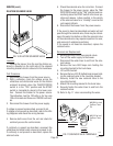
7. Remove the two hex nuts securing the tank heater
to the tank lid. Remove tank heater with gaskets
and discard.
8. Install new tank heater with gaskets on the tank
lid and secure with two hex nuts.
9. Install tank lid with limit thermostat, sprayhead
tube, tank heater, faucet tube and vent tube using
eight #8-32 nuts.
10. Secure sprayhead tube to hood using a hex nut.
11. Install sprayhead.
12. Connect vent tube to fitting.
13. Connect the faucet tube.
14. Reconnect the wires to the limit thermostat and
tank heater. See limit thermostat section in this
manual when reconnecting wires.
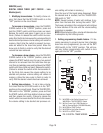
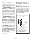
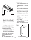
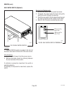
15. Refer to Fig. 25 when reconnecting the tank heater
wires.
FIG. 25 TANK HEATER TERMINALS
P1369
WHI to Power Cord
(120V Models) or
RED to Terminal
Block (120/208V
Models)
BLK to Control
Thermostat or
Thermal Fuse
10510 081599