


Page 24
SERVICE (cont.)
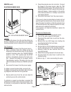
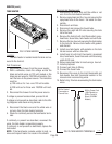
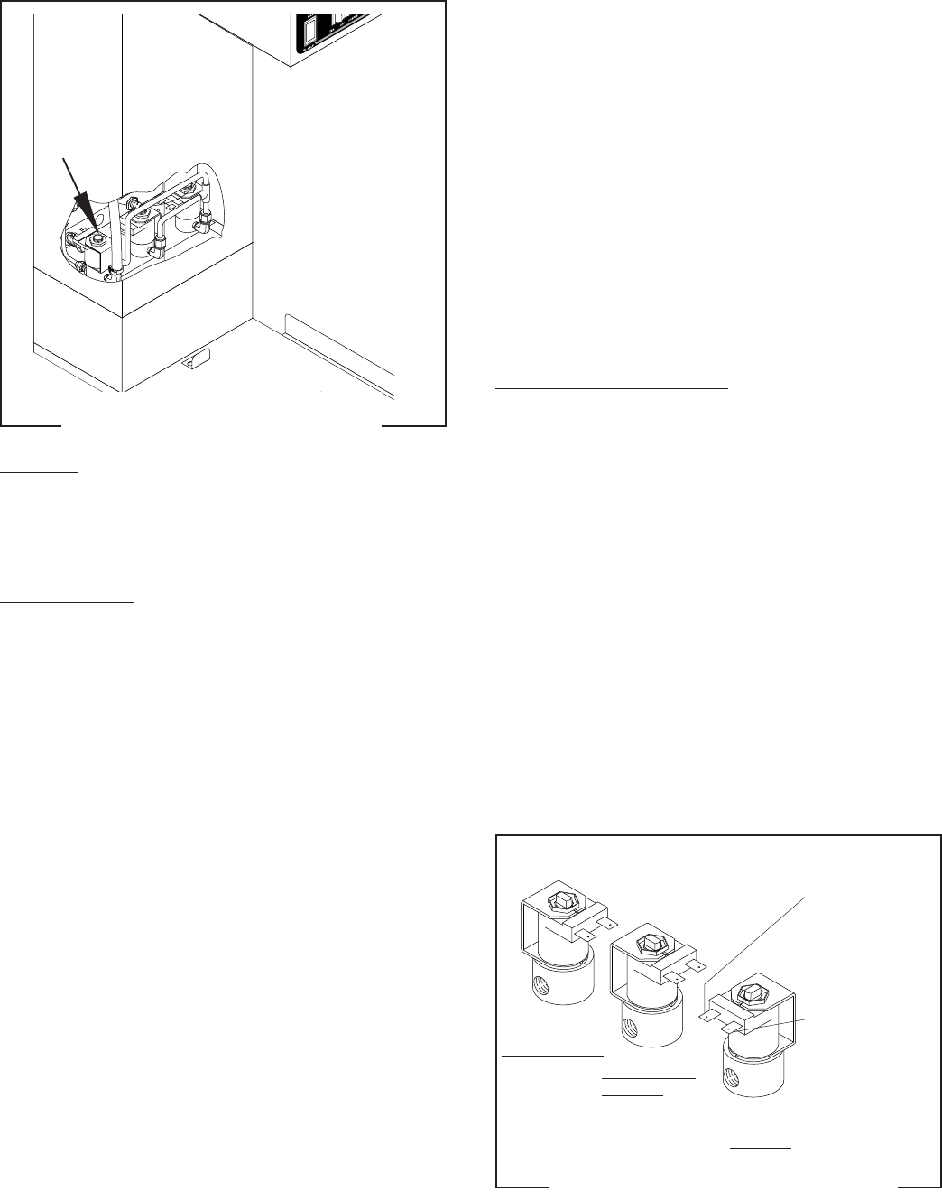
DILUTION SOLENOID VALVE
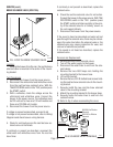
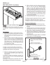
FIG. 16 DILUTION SOLENOID VALVE
P2198.50
Location:
Viewing the brewer from the rear the dilution so-
lenoid is mounted on the right side of the solenoid
mounting bracket which is secured to the trunk base.
Test Procedure:
1. Disconnect the brewer from the power source.
2. With a voltmeter, check the voltage across the
white/blue and white/violet wires on the dilution
solenoid terminals when the TEA/OFF/COFFEE
switch is in the “TEA” position and the START
switch is momentarily placed in the lower posi-
tion. Connect the brewer to the power source.
The indication must be 120 volts ac for two wire
120 volt models and three wire 120/208 volt mod-
els.
3. Disconnect the brewer from the power supply.
If voltage is present as described, proceed to #4.
If voltage is not present as described, refer to the
Wir-
ing Diagrams
and check the wiring harness.
4. Remove both wires from the coil and check for
continuity across the coil terminals.
If continuity is present as described, reconnect the
white/blue and white/violet wires and proceed to #5.
If continuity is not present as described, replace the
solenoid valve.
5. Check the solenoid valve for coil action. Connect
the brewer to the power source, place the TEA/
OFF/COFFEE switch in the “TEA” position and mo-
mentarily place the START switch in the lower po-
sition and release. Listen carefully in the vicinity
of the solenoid valve for a “clicking” sound as the
coil magnet attracts.
6. Disconnect the brewer from the power source.
If the sound is heard as described and water will not
pass through the solenoid valve, there may be a block-
age in the water line before or after the solenoid valve
or, the solenoid valve may require inspection for wear,
and removal of waterborne particles.
If the sound is not heard as described, replace the
solenoid valve.
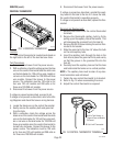
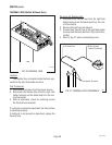
Removal and Replacement:
1. Remove all wires from the solenoid valves.
2. Turn off the water supply to the brewer.
3. Disconnect the water lines to and from the sole-
noid valves.
4. Remove the two #8-32 keps nuts holding the
mounting bracket to the trunk base.
5. Lift out the bracket.
6. Remove the two #10-32 slotted-head screws hold-
ing the solenoid valve to the mounting bracket.
7. Securely install the new solenoid valve to the
mounting bracket.
8. Attach the mounting bracket to the trunk base.
9. Securely fasten the water lines to and from the
solenoid valves.
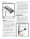
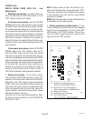
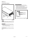
10. Refer to Fig. 17 when reconnecting the wires.
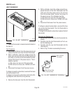
FIG.17 SOLENOID VALVE TERMINALS
P1364
HOT COFFEE
BREW SOLENOID
ICED TEA BREW
SOLENOID
DILUTION
SOLENOID
WHI/BLU to Iced
Tea Brew Timer
TL4
WHI/VIO to Iced
Tea Brew Timer
TL1
10510 081599