


Page 25
SERVICE (cont.)
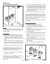
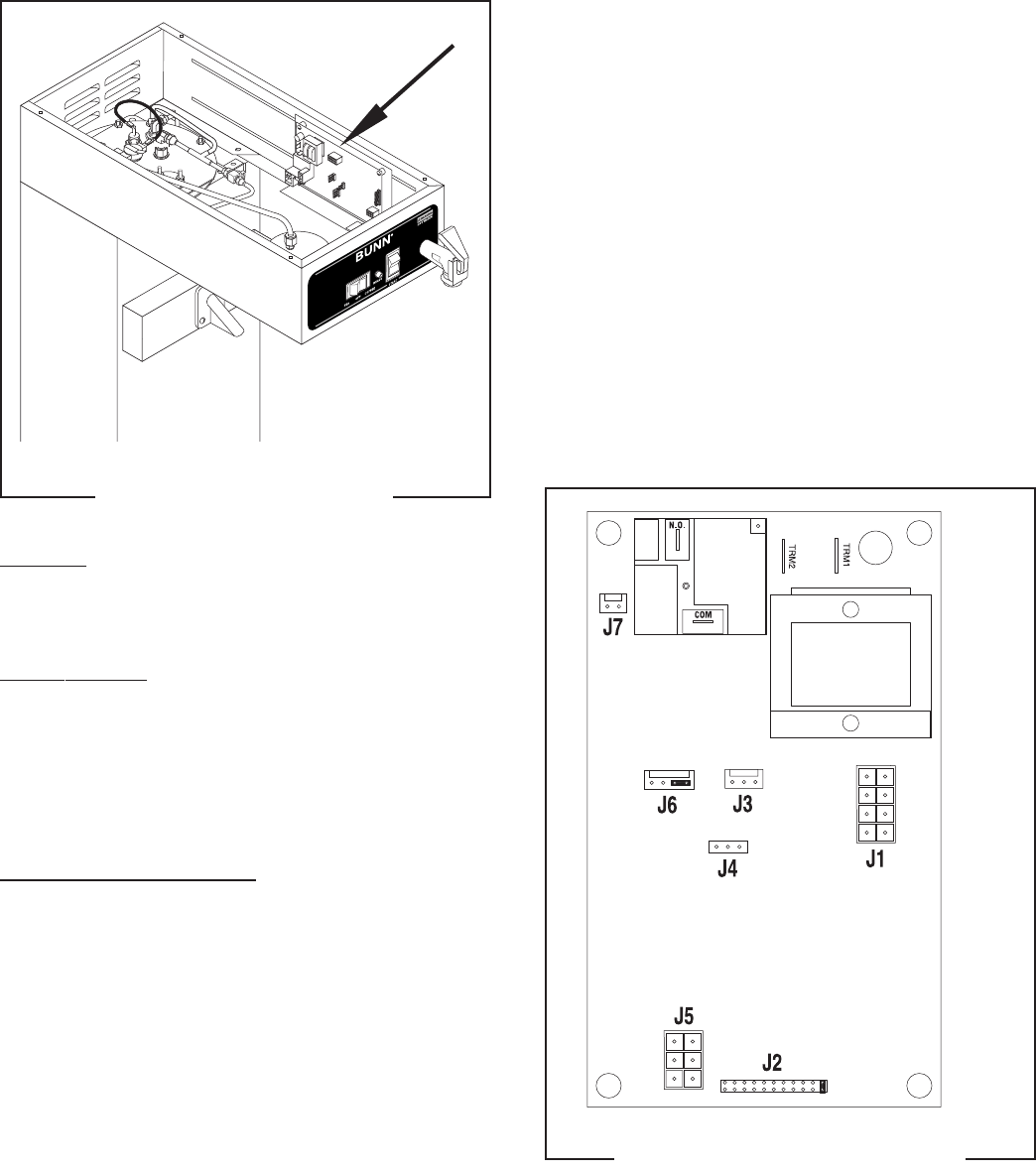
CONTROL BOARD
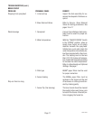
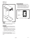
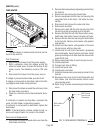
FIG. 20 CONTROL BOARD
P1960.50
TRM1
T
R
M
2
J
6
J
7
J3
J
1
J4
J2
J
5
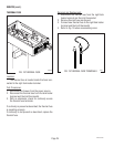
Location:
The Control Board is located inside the hood on
the right front behind the Start switch.
Test Procedure:
The test procedures for the control board will vary
depending upon the problems experienced by the
brewer. Refer to the Troubleshooting guide beginning
on page 8. The troubleshooting guide is divided into
two sections, Heating Circuit and Brewing Circuit.
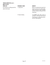
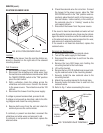
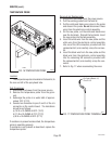
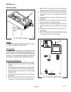
Removal and Replacement:
1. Disconnect the black wire (COM) to the cordset.
2. Disconnect the blue wire (N.O.) to the limit ther-
mostat.
3. Disconnect the 8-pin connector (J-1) and the 6-
pin connector (J-5) to the main wiring harness.
4. Disconnect the 2-pin connector (J-7) to the ready
indicator LED.
5. Disconnect the 3-pin connector (J-3) to the wir-
ing harness.
6. Remove the four #6-32 screws securing the con-
trol board to the component mounting bracket.
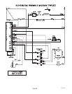
FIG. 21 CONTROL BOARD WIRING
P1803.75
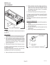
7. Remove the four spacers from the old control
board and attach them to the new control board.
8. Install the new control board and secure with the
four #6-32 screws to the component mounting
bracket.
9. Connect the 2-pin connector from the ready indi-
cator LED.
10. Connect the 8-pin connector and the 6-pin con-
nector from the main wiring harness.
11. Connect the blue wire (N.O.) from the limit ther-
mostat and the black wire (COM) from the cord
set.
12. Connect the 3-pin connector from the main wir-
ing harness.
11. Refer to
Adjustments and Optional Settings (Page
7)
to program the new control board.
29466 061599