


2
CONTENTS
Page
GENERAL. . . . . . . . . . . . . . . . . . . . . . . . . . . . . . . . . . . . . . . . . . . 2
UNIT INSPECTION. . . . . . . . . . . . . . . . . . . . . . . . . . . . . . . . . . 2
INSTALLATION . . . . . . . . . . . . . . . . . . . . . . . . . . . . . . . . . . . 2-5
LOCATE UNIT. . . . . . . . . . . . . . . . . . . . . . . . . . . . . . . . . . . . . 2
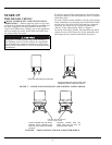
LEVEL UNIT . . . . . . . . . . . . . . . . . . . . . . . . . . . . . . . . . . . . . . 4
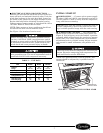
INSTALL SHELVES . . . . . . . . . . . . . . . . . . . . . . . . . . . . . . . . 5
CONDENSATE DISPOSAL. . . . . . . . . . . . . . . . . . . . . . . . . . 5
START-UP. . . . . . . . . . . . . . . . . . . . . . . . . . . . . . . . . . . . . . . . . 6,7
PRELIMINARY CHECKS. . . . . . . . . . . . . . . . . . . . . . . . . . . 6
INITIAL START-UP . . . . . . . . . . . . . . . . . . . . . . . . . . . . . . . . 7
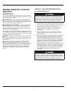
REFRIGERATION SYSTEM SERVICE . . . . . . . . . . . . 8-13
COMPONENTS . . . . . . . . . . . . . . . . . . . . . . . . . . . . . . . . . . . . 8
SERVICE AND TROUBLESHOOTING . . . . . . . . . . . . . . . 8
MAINTENANCE. . . . . . . . . . . . . . . . . . . . . . . . . . . . . . . . . 14,15
LAMP REPLACEMENT . . . . . . . . . . . . . . . . . . . . . . . . . . . 14
CONDENSATE REMOVAL . . . . . . . . . . . . . . . . . . . . . . . . 14
CONDENSER. . . . . . . . . . . . . . . . . . . . . . . . . . . . . . . . . . . . . 14
CABINET EXTERIOR . . . . . . . . . . . . . . . . . . . . . . . . . . . . . 14
INTERIOR SURFACE . . . . . . . . . . . . . . . . . . . . . . . . . . . . . 14
GENERAL
These instructions cover the installation, operation,
and maintenance of Carrier Miracool™ series glass
door merchandiser units, sizes 260L, 300L, 750L,
1100L, and 1300L.
UNIT INSPECTION
Examine all packages for damage to packaging mate-
rial. Damage to external packaging may have resulted
in unit damage. Check packages for all accessories and
components, including legs, casters, and shelves. File
a claim immediately with the shipping company if
shipment is damaged or incomplete.
INSTALLATION
LOCATE UNIT
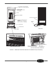
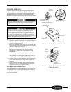
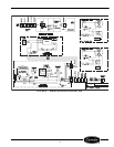
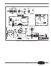
Refer to Figure 1 for unit components. Units are
designed for indoor placement only. Provide at least
3 in. of space between unit cabinet and any adjacent
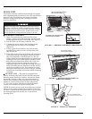
wall or fixture. Remove skid base by removing the
retaining screws (4 hex head bolt screws). If optional
casters will be used, unit must be located on flat, level
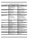
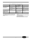
surface. Refer to Table 1 for a list of standard parts.
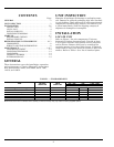
TABLE 1 — STANDARD PARTS
NOTE: Parts shown are for standard units. Quantity of shelves and clips may vary based on factory-supplied options.
PART
FACTORY
INSTALLED
FIELD
INSTALLED
UNIT SIZE
260L, 300L 750L 1100L, 1300L
Quantity
Refrigeration Cartridge X111
Shelves X4510
Shelf Clips X162040
Instruction Manual ——111
Leveling Feet X444
Lamps X122