


4
LEVEL UNIT
To provide adequate condensate drainage and proper
door alignment and operation of unit, the unit cabinet
must be level. Leveling feet are factory installed.
Remove refrigeration system cartridge for easier
access to back feet.
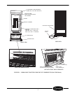
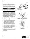
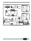
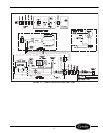
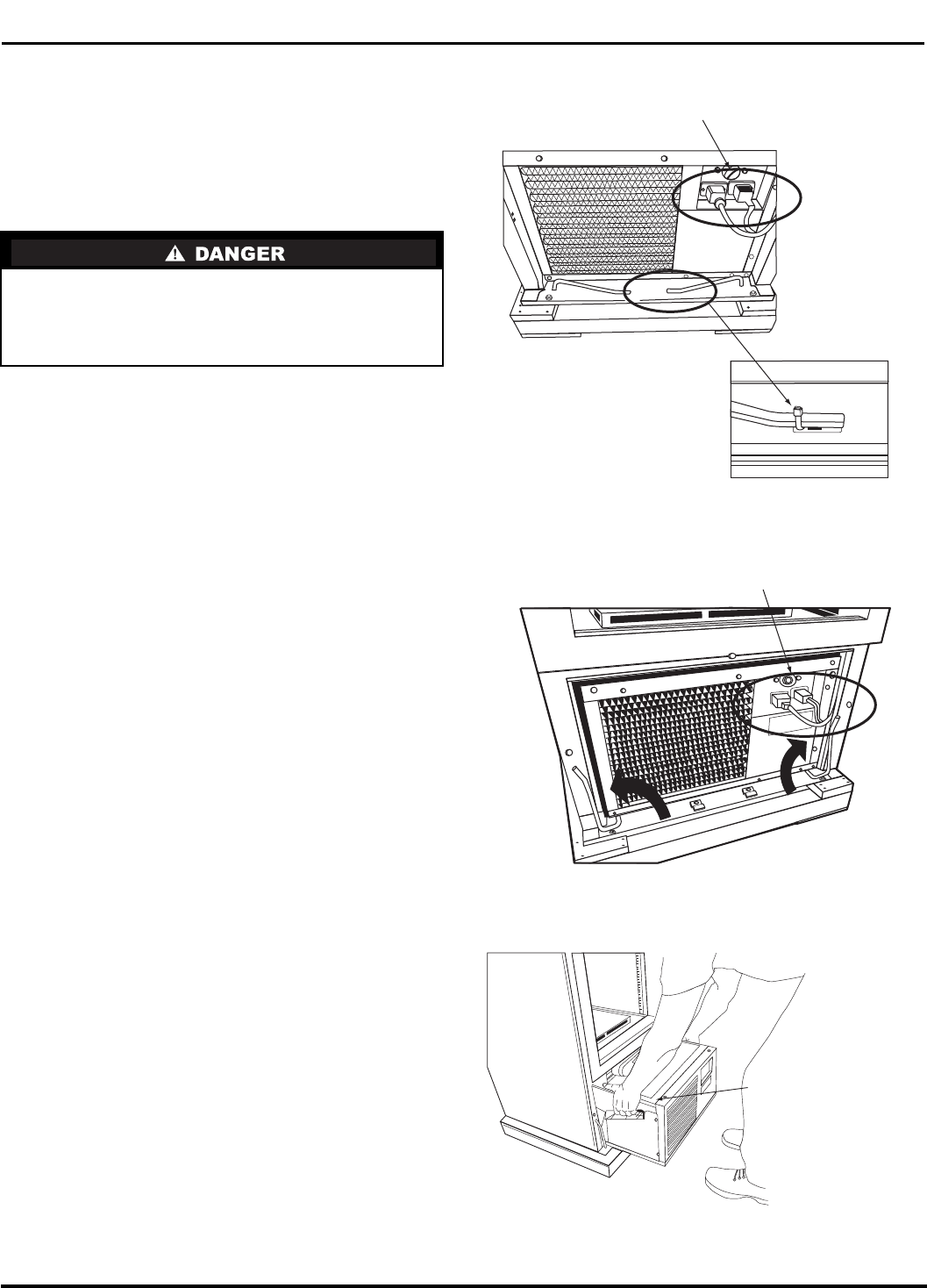
TO REMOVE CARTRIDGE
1. After disconnecting the unit from the power
supply, remove the grille retaining screw located
in the upper-most part of the grille. (See Figure 1.)
2. Lift the grille up and away from the unit.
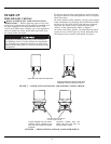
3. Unplug the power supply and lighting supply
cords located in the front of the cartridge
(Figure 2).
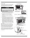
4. Using a pair of wire cutters, cut wire tie that
secures lifting rods at center of front base rail.
(See Figure 2.)
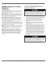
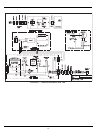
5. Take hold of the end of each lifting rod and rotate
each approximately 90-degrees upward so that
they are nominally vertical (Figure 3.) The car-
tridge should be disengaged from the cabinet and
resting on the base of the cabinet assembly. Han-
dling holes are located on either side of the car-
tridge near the top and along the side of the
cartridge (Figure 4). Grasp the cartridge by these
holes and slide the unit forward from the cabinet
until the cartridge is free. Use caution to ensure
that power and electrical cords do not get pinched
between the cartridge and cabinet while removing
cartridge.
TO LEVEL UNIT — The door is equipped with
gravity assisted cams and will not function properly
without proper leveling of cabinet. Adjust feet using
adjustable wrench so that unit sits approximately
level to floor and door closes properly. For best door
operation, adjust leveling feet so that cabinet has
a
1
/
16
-in. rake or slant from front to back. Optional
casters are available to replace leveling feet.
NOTE: If casters are not used, local codes may require
cabinet to be sealed around the perimeter of the cabi-
net base. Consult local sanitation codes. Use only seal-
ant material approved for this use, such as Dow
Corning #732.
Before servicing unit, disconnect electrical service.
On sizes 1100L and 1300L, turn disconnect switch
(located on power cord) to the OFF position. Failure
to disconnect electrical service could result in elec-
trical shock and cause personal injury or death.
CARTRIDGE POWER
AND LIGHTING CORDS
PULL THE CARTRIDGE USING
THE HANDLING HOLES ON SIDES
UNPLUG CARTRIDGE POWER
AND LIGHTING CORDS
FIGURE 2 — PREPARE CARTRIDGE FOR REMOVAL
FIGURE 3 — ROTATE LIFTING WIRES IN
DIRECTION SHOWN
FIGURE 4 — REMOVE CARTRIDGE
CUT WIRE TIE THAT SECURES
LIFTING RODS TO BASE
a79-2
a79-3
a79-4