


7
ELECTRICAL SUPPLY AND CONNECTIONS —
Check to be sure that the electrical service to the unit
meets all local and national electrical codes. Unit elec-
trical data is shown in the unit data label, located on
the inside of the cabinet in the upper lefthand corner.
Review this label before initiating electrical service.
Voltage range of power supply to unit should be 105 to
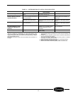
125 volts. Refer to Table 2 for unit data.
NOTE: Other motors or heavy appliances should not
be used on the same circuit with the cooler.
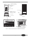
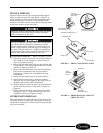
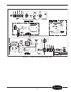
See Figure 1 for location of service cord.
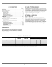
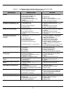
TABLE 2 — UNIT DATA
INITIAL START-UP
POWER SUPPLY — Connect unit to power supply.
On sizes 1100L and 1300L, turn disconnect switch to
the ON position. Check to verify that the compressor,
lamp, and fans are running.
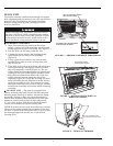
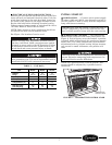
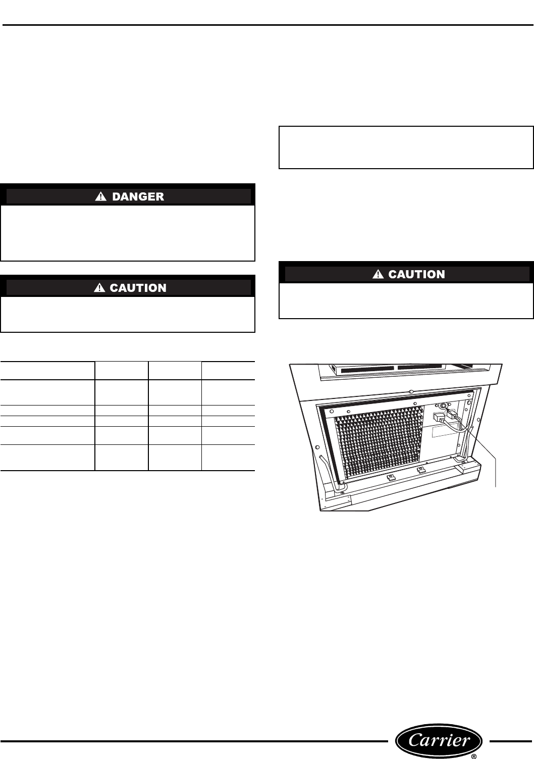
TEMPERATURE CONTROL — The temperature
control knob is located in the front power panel. See
Figure 9. Unit is factory set at the number 4 position
(normal), which will maintain the product at approxi-
mately 38 F. For colder temperature, turn the black
adjustment knob to a higher setting. Adjust tempera-
ture control in small increments, one position at a
time.
NOTE: For operation above 3,000-ft altitude, ther-
mostat should be adjusted by a qualified service
technician.
Before servicing unit, disconnect electrical service.
On sizes 1100L and 1300L, turn disconnect switch
(located on power cord) to the OFF position. Failure
to disconnect electrical service could result in elec-
trical shock and cause personal injury or death.
If an extension cord is necessary, use only three-
wire grounding type. The use of ungrounded cords or
overloaded circuit voids compressor warranty.
UNIT
MC260,
MC300
MC750
MC1100,
MC1300
Voltage
Nominal 115 115 115
Range 105-125 105-125 105-125
Frequency 60 60 60
Total Amps 4.6 8.9 10.6
Refrigerant Type R-134A R-134A R-134A
Charge Amount (oz) 4.3 7.5 14.5
Design Pressure
High Side (psig) 220 265 222
Low Side (psig) 88 93 88
IMPORTANT: Low line voltage is often the cause of
service complaints. Check to see that the line volt-
age is within specified range with the unit running.
Allow 24 hours between temperature control adjust-
ments. Excessive tampering with temperature con-
trol could lead to service difficulties.
TEMPERATURE
CONTROL KNOB
FIGURE 9 — TEMPERATURE CONTROL KNOB
a79-9