


8
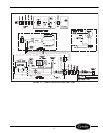
REFRIGERATION SYSTEM
SERVICE
COMPONENTS
The Carrier Miracool™ refrigeration system consists
of a hermetically sealed compressor and finned evapo-
rator and condenser coils.
CONDENSER — The condenser has wide finned
spaces, which allow more air passage with less dirt or
dust accumulation. The condenser still requires peri-
odic cleaning for maximum efficiency.
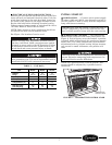
CONDENSER FAN MOTOR — The condenser fan
motor assembly is mounted between the condenser
and the compressor. Air is drawn through the con-
denser, over the body of the compressor and out the
rear of the unit compartment.
The motor is wired to cycle with the compressor but
will continue to operate should the compressor cut out
on the overload. (The motor is permanently lubricated;
therefore, oiling is not required.)
DRIER — The drier is installed in the system just
before the capillary tube. The drier traps minute parti-
cles of foreign material and absorbs any moisture in
the system.
LIQUID CONTROL AND HEAT EXCHANGER —
Liquid refrigerant control to the evaporator of the
system is accomplished by the use of a capillary tube.
This capillary tube is soldered to the suction line to
form a heat exchanger, which subcools the liquid
refrigerant to maintain high efficiency within the
system.
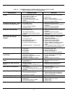
SERVICE AND TROUBLESHOOTING
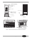
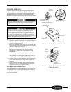
CARTRIDGE REMOVAL
1. After disconnecting the unit from the power
supply, remove the grille retaining screw located
in the upper-most part of the grille. (See Figure 1.)
2. Lift the grille up and away from the unit.
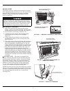
3. Unplug the power supply and lighting supply
cords located in the front of the cartridge
(Figure 2).
4. Using a pair of wire cutters, cut wire tie that
secures lifting rods at center of front base rail.
(See Figure 2.)
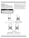
5. Take hold of the end of each lifting rod and rotate
each approximately 90-degrees upward so that
they are nominally vertical (Figure 3). The car-
tridge should be disengaged from the cabinet and
resting on the base of the cabinet assembly. Han-
dling holes are located on either side of the car-
tridge near the top and along the side of the
cartridge (Figure 4). Grasp the cartridge by these
holes and slide the unit forward from the cabinet
until it is free. Use caution to ensure that power
and electrical cords do not get pinched between
the cartridge and cabinet while removing
cartridge.
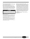
Before servicing unit, disconnect electrical service.
On sizes 1100L and 1300L, turn disconnect switch
(located on power cord) to the OFF position. Failure
to disconnect electrical service could result in elec-
trical shock and cause personal injury or death.
Before servicing unit, disconnect electrical service.
On sizes 1100L and 1300L, turn disconnect switch
(located on power cord) to the OFF position. Failure
to disconnect electrical service could result in elec-
trical shock and cause personal injury or death.