


5
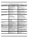
INSTALL SHELVES
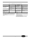
Product shelves and a bag containing shelf support
clips are packed inside the unit. Refer to Table 1 to
verify quantity of shelves and shelf supporting clips.
Bottom shelf must be placed on interior floor and
should be inserted into the two retainer clips provided
at the rear corners of the unit floor.
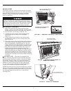
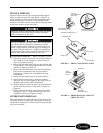
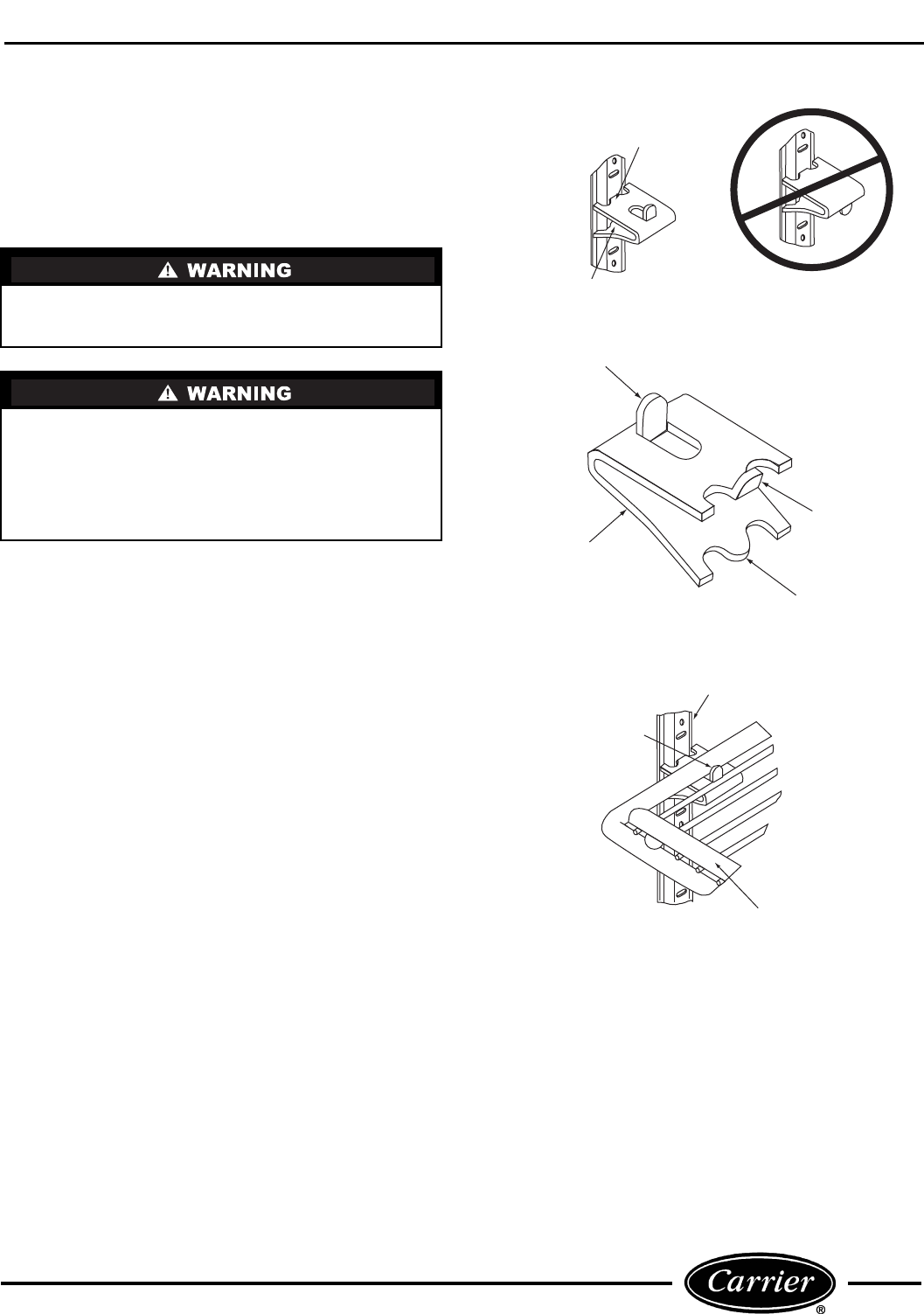
TO INSTALL SHELVES — Refer to Figures 5 and 6.
1. Determine proper location for shelf clips. Refer to
the numbers on the pilaster to ensure that all
clips are properly located.
2. Insert top tab of the shelf clip into the desired hole
of the pilaster. The retaining tab should be facing
upward as shown in Figure 5.
3. Rotate the clip downward and insert the bottom
tab into the appropriate hole on the pilaster.
If necessary, squeeze the clip slightly during
installation.
4. Install all remaining clips as described above.
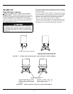
5. Install shelves onto clips so that the product
retention bar is facing upward. Be careful not to
dislodge clips during shelf installation.
6. Shelves must be placed so that the retaining tab
on the shelf clip captures the shelf as shown in
Figure 6.
7. Before loading the shelf, ensure that the shelf is
resting on each of 4 clips and that the clips are
installed as shown in Figures 5 and 6.
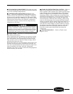
CONDENSATE DISPOSAL
The evaporator drain pan is located in the base of the
cartridge. Airflow in cartridge compartment hastens
condensate evaporation so that external drain plumb-
ing is not required.
Improper shelf clip installation may cause shelf and/
or product to fall which could result in personal
injury or damage to the unit.
Do not overload the shelves. The unit is designed to
use all the shelves provided, installed in equally
spaced configuration. Failure to install shelves cor-
rectly could result in personal injury or damage to
the unit. If fewer shelves or a different installation
configuration is desired, contact the manufacturer to
ensure that shelf overloading will not occur.
PRODUCT
RETENTION BAR
SHELF
RETAINED
BY TAB
PILASTER
TOP TAB
FULLY INSERTED
INTO SLOT
BOTTOM TAB
FULLY SEATED
IMPROPERLY INSTALLED
CLIP (UPSIDE DOWN)
RETAINING TAB
SHELF CLIP
TOP TAB
BOTTOM TAB
PROPERLY INSTALLED CLIP
FIGURE 5 — SHELF CLIP INSTALLATION
FIGURE 6 — PROPER INSTALLATION OF
SHELF ON CLIP
a79-5
a79-6