


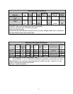
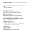

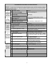
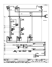

TEST
T5
N
L1
4
3
2
1
T5
N
L1
4
3
2
1
T5
N
L1
4
3
2
1
T5
N
L1
4
3
2
1
T5
N
L1
4
3
2
1
T5
N
L1
4
3
2
1
T5
N
L1
4
3
2
1
T5
N
L1
4
3
2
1
T5
N
L1
4
3
2
1
T5
N
L1
4
3
2
1
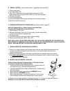
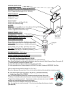
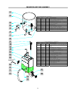
A) Water Inlet Valve Test
Check Valve
Ass’y L463A
Check Valve
Ass’y L463A
Check Valve
Ass’y L463A
Turn power off. If the water level rises inside the tank, the Water Inlet Valve
is leaking. Disconnect wires from the Water Inlet Valve coil and connect a 2 wire
line cord to the terminals. Plug it into a 115V outlet. If water flows in and stops
when you pull it out, the Valve is working fine. Repeat this test a few times. The
problem may be in the Probe or Water Level Control Board. If the water does
not flow in when the cord is plugged into an electrical outlet, the Solenoid coil
may be damaged, opened or the valve may have an obstruction preventing the
water from flowing in. Clean or replace it.
Hose Nut Ass’y K491A
K491B was K178A
Water Inlet
Valve [.5gpm]
CD257 110V
CD258 220V
[was L462A]
Water Inlet
Valve [.5gpm]
CD257 110V
CD258 220V
[was L462A]
Water Inlet
Valve [.5gpm]
CD257 110V
CD258 220V
[was L462A]
Water Inlet
Valve [.5gpm]
CD257 110V
CD258 220V
[was L462A]
A Check Valve is installed to prevent backflow.
To check proper function of Check Valve, disconnect water line from the Check
Valv
e, check for dripping from the disconnected end of the Check Valve.
If it leaks replace it.
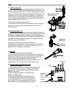
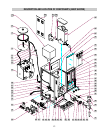
B) Hi-Level Float Switch Test
The Float Switch acts as a guardian for the Solid State Level Control Board
an
d its Probe. If they malfunction and cause the water inside the tank to rise, the
Float Switch will prevent flooding by terminating the power to the Solid State
Control Board and the Water Inlet Valve. The correct mounting position of the
Float Switch in the tank is as shown in picture, with the magnets in the Float
Switch in the upper part of the switch.
Float Switch
L499A [70VA]
Correct Position
of Magnets
After tank is full, unplug the wire to th
e Level Control Probe,
the water should run into the tank for a few more seconds until it reaches the
Float Switch and it should stop. If not, and wat
er starts coming out of the
Breather tube, the Float Switch is malfunctioning.
C) Probe Test
If lack of water persists, check the probe as follows:
Turn on the power and water supply. Check inside the tank to make sure the
wat
er is not touching the Probe. Pull wire and terminal out of the Probe rod. If
water still does not flow after the wire is disconnected from the Probe, the
problem may be in the Solid State Water Level Control Board.
Level Control Probe
K402Q
Level Control Probe
K402Q
Level Control Probe
K402Q
If water starts flowing into the tank, the Probe may be grounded, due to
excessive liming. Check with Ohm meter. Clean or replace probe.
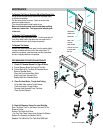
To Solenoid
D) Solid State Water Level Control Board Test
Check the Board as follows:
To Probe
1. Make sure there is power input to the Board at the terminals 2 & 3
Your voltmeter should read 115 Volts. It should read the same at
terminals 1 &
3. This is the output power to electrify the coil of the
Solenoid Valve to open it.
The lack of voltage at terminals 2 & 4 will indicate that the
Boa
rd is not working properly.
Grounding
Plate in
Back of Board
Ground
terminal
2. Make sure all wire connections to the Board are tight.
3. The gr
ounding plate at the top, in the back of the board
should be securely grounded. The Board will not work or will
work erratically, if it is not grounded properly. If after this, the
Board is still failing to open the Water Inlet Valve, replace it.
Water Level Control Board
7