Vermont Castings, Majestic Products
12 DVR33 10002823/0
VENTING INSTALLATION INSTRUCTIONS
GENERAL INFORMATION ON
ASSEMBLING THE VENT PIPES IN
DIRECT VENT APPLICATIONS.
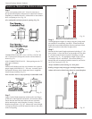
Crimped End Pipes
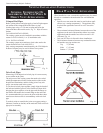
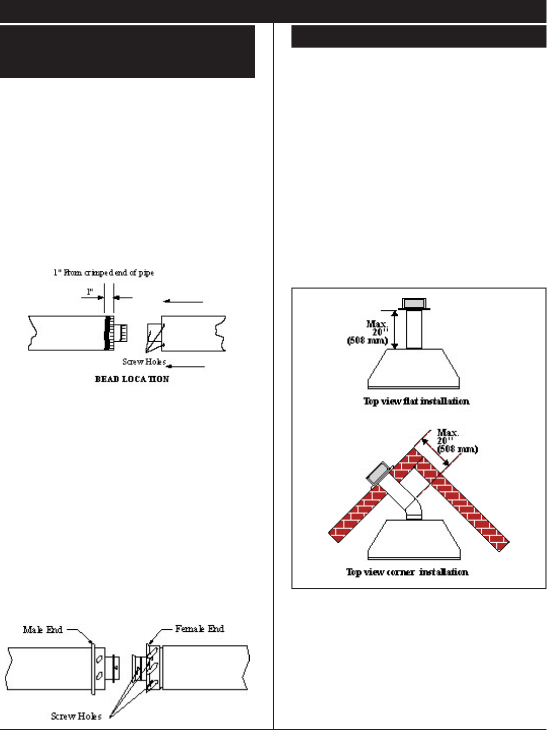
Before joining elbows and pipes apply a bead of high tempera-
ture sealant to the crimped end of the elbow or pipe.
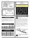
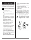
Join the pipes using a 2" (50 mm) overlap and secure the
joints with three sheet metal screws, Fig. 12. Wipe off excess
sealant.
CANADIAN INSTALLATIONS:
The venting system must be installed in accordance with the
current CAN/CGA-B149 (.1 or .2) installation code.
U.S.A. INSTALLATIONS:
The venting system must conform to local codes and/or the
current National Fuel Code ANSI Z223.1.
Only venting components manufactured by the CFM Majestic
Products Company may be used in Direct Vent systems.
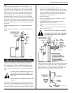
Twist Lock Pipes
When using CFM Majestic twist lock pipe it is not necessary
to use sealant on the joints.
The only areas of the venting system that need to be sealed
with high temperature silicone sealant are the collars on the
replace and termination, and the sliding joint of any tele-
scopic vent section used in the system.
To join the twist lock pipes together, simply align the beads of
the male end with the grooves of the female end, then while
bringing the pipes together, twist the pipe until the ange on
the female end contacts the external ange on the male end.
It is recommended that you secure the joints with three sheet
metal screws however this is not mandatory with twist lock
pipe.
To make it easier to assemble the joints we suggest putting a
lubricant (Vaseline or similar) on the male end of the twist lock
pipe prior to assembly.
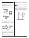
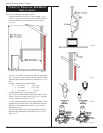
REAR WALL VENT APPLICATION
When installed as a rear vent unit this appliance may be vented
directly to a termination located on the rear wall behind the
appliance.
• Specic rear vent starter kits must be used in these appli-
cations (see ‘venting components’). The appliance may
be placed at against the rear wall or at 45º across the
corner.
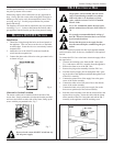
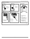
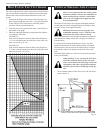
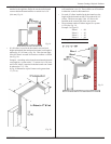
• The maximum horizontal distance between the rear of the
appliance (or the end of the transition elbow in a corner
application) and the outside face of the rear wall is 20"
(508 mm), Fig. 14.
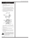
• Only one 45º elbow is allowed in these installations
• The minimum clearances between any combustible mate-
rial and the vent pipe sections are:
Top 2" (50 mm)
Sides 1" (25 mm)
Bottom 1" (25 mm)
Fig. 12
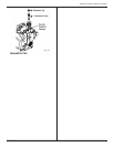
Fig. 13
Fig. 14


