Vermont Castings, Majestic Products
16 DVR33 10002823/0
VERTICAL SIDEWALL INSTALLATIONS
Step 1
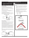
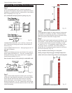
Locate vent opening on the wall. It may be necessary to
rst position the replace and measure to obtain hole location.
Depending on whether the wall is combustible or non-combus-
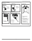
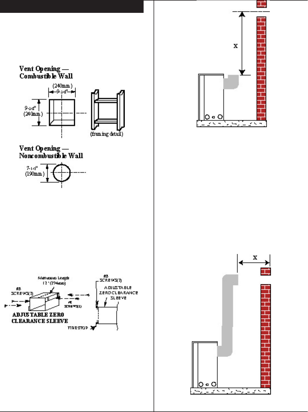
tible, cut opening to size. (Fig. 22)
(For combustible walls rst frame in opening. Fig. 22).
COMBUSTIBLE WALLS : Cut a 9-3/8"H x 9-3/8"W (240
mm x 240 mm) hole through the exterior wall and frame as
shown (Fig. 22).
NON-COMBUSTIBLE WALLS : Hole opening must be 7.5"
(190 mm) in diameter.
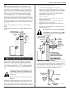
Step 2
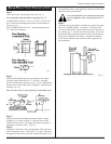
Measure wall thickness and cut zero clearance sleeve parts to
proper length (MAXIMUM 12" / 305 mm). Assemble sleeve
and attach to restop with #8 sheet metal screws (supplied).
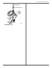
Install restop assembly (Fig. 23).
Zero clearance sleeve is only required for combustible walls.
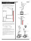
Step 3
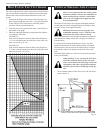
Apply a bead of high temperature sealant to the vent anges
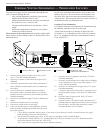
on the back of the appliance and attach a 90º transition elbow.
Ensure that the inner and outer elbow ends are concentric
before attaching the vertical lengths of venting. Place the
replace into position. (Fig. 24). Measure the vertical height
(X) required from the end of the transition elbow to the centre
of the wall opening.
Step 4
Attach appropriate lengths of venting using the joining meth-
ods outlined in 'Assembling Vent Pipes'. When the desired
height has been reached attach the top inner and outer elbow,
again secure joints as described on page earlier.
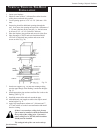
Step 5
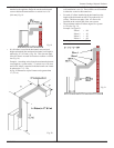
Measure the horizontal length requirement including a 2" (50
mm) overlap, i.e. from the elbow to the outside wall face plus
2" (50 mm) (or the distance required if installing a second
90º elbow. (Fig. 21). Use appropriate length of pipe sections
- telescopic or xed - and install. The sections which go
through the wall are packaged with the starter kit, and can be
cut to suit if necessary. (Fig. 25).
Always install horizontal venting on a level plane.
Sealing vent pipe and restop gaps with high temperature
sealant will restrict cold air being drawn in around replace.
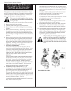
Fig. 22
Fig. 23
Fig. 24
Fig. 25


