


10 10005360
LHE Series Natural Vent Insert
Ceramic Refractory Installation
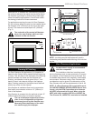
1. Remove front glass.
2. Remove logs from unit.
3. Remove refractory from package.
Refractory are fragile and must be handled
with care. Where at all possible, two hands
should be used when handling.
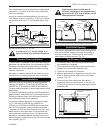
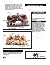
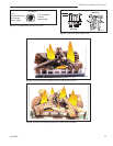
4. Take center refractory and tilt so bottom edge seats
onto the rear log bracket at the back wall of the fire
-
place. (Fig. 15)
5. Press center refractory to back side of fireplace and
hold in place.
6. Take left or right refractory and align it so leading
edge faces outward. (Place refractory in fireplace
side and slide it back to support the center refrac-
tory.)
7. Repeat step 6 for remaining side refractory.
8. Fasten bracket supports against refractory top to
hold side in place.
When side refractory is installed correctly,
the center refractory will be supported by
the side refractory.
FP1329
LHEDV
ceramic refractory
4/03
Leading Edge
Leading Edge
Left Side
Right Side
Center
FP1329
Fig. 15 Ceramic refractory.
Bottom Edge
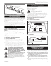
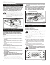
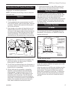
Blocked Flue Shut Off System
These inserts are equipped with a blocked flue shut off
switch. This switch is factory installed, wired and tested.
Check and make sure the switch and wires are in the
proper position. The shut off switch is heat activated
and wired in series with the pilot system. (Fig. 13)
Operation of this fireplace when not con
-
nected to a properly installed and main-
tained venting system or tampering with
the blocked flue shut-off system can result
in carbon monoxide (CO) poisoning and
possible death.
Blocked Flue Shut Off Switch Access
The shut off switch system of these inserts is designed
to be accessed from either inside the combustion
firebox chamber or outside at the back of the inserts
fireplace.
Access to the shut off switch from outside of the
insert
1. Turn off the unit and let it cool down if it has been
operating.
2. Shut off the gas and the electrical source to the fire
-
place.
3. Disconnect the gas line and the draft hood of the
fireplace.
4. Slide the fireplace out.
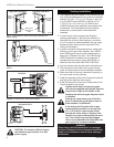
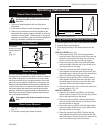
Access to the shut off switch directly from inside
the combustion firebox chamber.
1. Turn off the unit and let it cool down if it has been
operating.
2. Remove the log set and remove the ceramic refrac
-
tory if installed.
3. Remove the firebox baffle. (Fig. 14)
4. Remove the shut off switch cover fastened with four
(4) screws located at the right upper corner of the
firebox.
5. This time you can access the shut off switch as
-
sembly through the rectangular opening. Remove
the screw that secures the switch assembly. Holding
the bracket switch carefully pull out the entire switch
assembly.
NOTE: The shut off switch cover was attached with the
gasket cover. Before installing the gasket cover back in
place, inspect and make sure the gasket is not dam-
aged. If the gasket is damaged, install a new gasket.
FP1352
Vent safety switch
5/03
Screws
Cover
Safety
Switch
Gasket Cover
Safety Switch
Bracket Shut
Off Switch
Screw must be removed prior
to pulling the switch assembly
Screws
Firebox Baffle
Screws
FP1352
Fig. 14 Access to the blocked flue shut off swtich from inside
combustion chamber.
FP1356
Vent safety switch
location
5/03
Blocked Flue Shut Off
Switch
Bracket
FP1356
Fig. 13 Blocked flue shut off switch location.