


9
10005360
LHE Series Natural Vent Insert
Zero clearance kit minimum clearance to combustibles
materials is 1" (25 mm) for B Vent (use of single wall
vent is not allowed.)
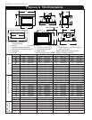
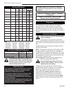
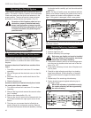
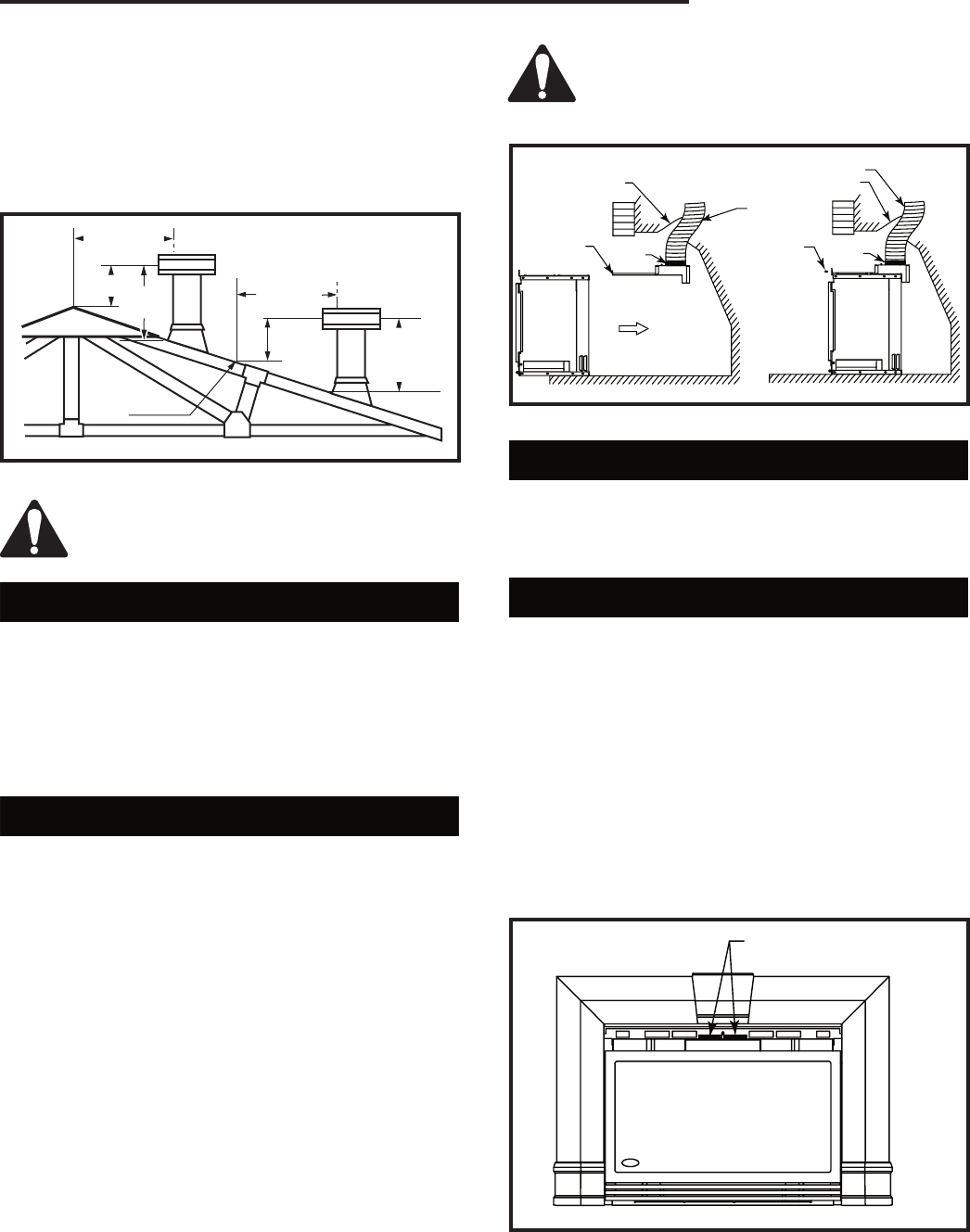
As with any natural drafted appliances, the vent cap
must always extend a minimum of 2' (610 mm) above
any structure within a 10' (3 m) horizontal plane. (Fig.
10)
2' Min.
2'
(610mm)
Min.
3'
Min.
0 To 10'
3'
(914mm)
Min.
0 To 10'
AC246
4/1/96
Reference
Point
(3m)
Fig. 10 Example of the 2', 3', 10' rule.
AC246a
A minimum 12' (3.7 m) vent height is re-
quired to effectively vent these fireplaces.
Common Flue Installations
In some areas it is possible to vent more than one gas
appliance into the same flue. You must ensure that the
flue being shared has the proper capacity to handle
both appliances. Check installation codes for venting
capacity information.
As always it is best to check with the authority having
jurisdiction prior to commencement of the installation.
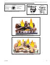
Liner Installation
Insert liner from top of chimney through the damper
opening and attach to 3" flue collar for LHEC20 and
LHER20 and 4" flue collar for LHEC30 and LHER30.
For best results use three (3) sheet metal screws and a
hose clamp.
For natural draft inserts, packing noncombustible fiber-
glass insulation around the liner in the damper area will
isolate the fireplace cavity from the chimney and pre-
vent drafts and noises during operation.
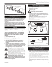
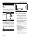
In case the fireplace opening is only minimum height
(17¹⁄₄" (438 mm) for LHEC20 and LHER20; 21"
(533mm) for LHEC30 and LHER30) and access from
the front is not possible, remove the flue collar plate
- unscrew and slide out from the back of the unit. Now
attach the liner to the flue collar, lift up and slide flue
collar plate back onto the unit top. It is important that
the plate is completely inserted and the front screw is
fastened again in order to line up the flue outlet and the
liner properly. (Fig. 11)
If the fireplace lintel is wider than 8"
(203 mm), the height of the fireplace open
-
ing must be 25" (635 mm) to allow for a 90°
offset elbow to be installed.
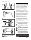
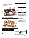
Draft Relief Opening
This insert is equipped with a draft-relief opening which
receives its dilution air supply through the opening at
the back of the insert. These openings must not be
obstructed or entered any way. (Fig. 12)
Test Chimney Draw
1. A "Chimney Draw" test must be conducted before
the installation is complete.
2. Close all doors and windows in the home and start
exhaust fans in he kitchen and bathroom.
3. Light unit and operate for 5 minutes.
4. Hold an ignited match or cigarette in front of the unit.
Refer to drawing for the location of the draft hood
opening. (Fig. 12)
5. Check to make sure smoke from the match or
cigarette is drawn into the fireplace. If it is not, turn
the unit off and check for causes creating the lack of
adequate draft.
FP1354
Flue outlet
5/03
Damper
Draft
Hood
Clamp
Chimney
Liner
Screw
Damper
Chimney Liner
Clamp
ST1354
Fig. 11 Remove flue collar plate and attach to flue collar.
Fig. 12 Hold an ignited match in front of fireplace.
Test for draft at these two
openings.
FP1355