


7
10005360
LHE Series Natural Vent Insert
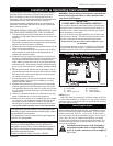
FP297
INSTA VENT FREE
R MODEL GAS SUPPLY
8/24/96
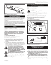
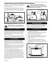
1/2" Gas Supply
1/2" x 3/8" Shut Off Valve
3/8" Nipple
3/8" Union
FP297
Fig. 4 Typical gas supply installation.
3/8" Nip-
ple
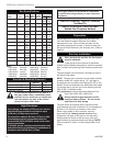
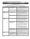
Gas Supply Pressures
This heater must be isolated from the gas supply piping
system by closing its individual manual shut-off valve
during any pressure equal to or less than 1/2 psig
(3.45kPa).
The heater and its individual shut-off valve must be
disconnected from the gas supply piping system during
any pressure testing of that system at test pressures in
excess of 1/2 psig (3.45kPa).
Fan Kit
115 volt, 60 Hz. 56w (Model FK24)
NOTE: The LHER20 and LHER30 are not designed for
a fan kit.
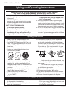
The fan kit includes the following: fan, temperature
sensor, speed control and a 6 ft. cord. The following
explains how to start and set the fan for automatic
operation.
1. Plug in the electrical cord.
2. Start gas fire - see lighting procedures.
3. Turn on fan speed control.
4. Wait until the unit has warmed up sufficiently to
activate the temperature sensor, approx. 5-10
minutes.
5. Once fan starts, adjust speed control to desired fan
speed. The fan will now automatically come on every
time the fireplace is in operation. Should the fan not
be needed simply turn off the speed control.
The appliance, when installed must be
electrically connected and grounded in
accordance with local codes or, in the ab-
sence of local codes, with the current CSA
C22.1 Canadian Electrical Code.
U.S. Installations, follow local codes and the
National Electrical Code, ANSI/NFPA No. 70.
Should this fan require servicing, the
power supply must be disconnected. For
rewiring of any replacement components
refer to Figure 6.
Fan Removal Instructions
1. Turn off gas and electricity.
2. Remove the front glass.
3. Remove the logs.
CAUTION: Logs may be hot!
4. For Model LHEC20: remove burner assembly and
bracket rear log. For Model LHEC30: remove brack-
et rear log and cover fan.
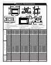
5. Remove the fan mounting nuts (2 nuts). (Fig. 5)
6. Slip off the electrical connector at the motor.
7. Lift out the fan.
8. To reinstall reverse procedure.
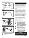
FP1252
FK24 install
1/03
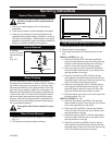
Thermal Sensor is
Attached to Burner
Base
Fan is Installed
at the Back of the
Air Intake Box
Fan Speed Control/Junction Box
Screw
Stud
Screw Stud
FP1252
Fig. 5 Fan location.
FP394
WIRING DIAGRAM
11/20/96
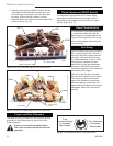
Fan
Temperature Sensor
Speed
Control
Black
White
Ground
FP394
Fig. 6 Wiring diagram RN/RP. NOTE: For comfort valve wir-
ing diagram refer to Page 18, Figure 27.
Installation of Trim Switch
for RN/RP Gas Valves
1. Thread wire through openings on the right side of fire-
place. Do not cut wire or insulation on metal edges.
2. Insert ON/OFF switch with wiring assembly into the
bracket switch with the pre-punched opening mounted
on the right side of the trim. (Fig. 7)
3. For left side installation, relocate the bracket switch
to the left side of the trim kit and repeat Step 2. (Fig.
8)
4. Connect wiring from the switch to the gas valve (Fig.
9a & b).