


5
10005360
LHE Series Natural Vent Insert
When the unit is installed into a woodburning fireplace,
the minimum distance the mantel can be placed above
the fireplace is governed by local building codes appli-
cable to woodburning fireplaces. Consult local authori-
ties having jurisdiction for these clearances.
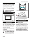
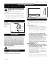
For applications requiring the use of a Zero Clearance
Kit, the minimum height a mantel can be installed above
the fireplace is 24" (610mm) from the top of the upper
louvres. The maximum mantel depth is 8" (200mm).
(Fig. 2)
The underside of the mantel will become
warm. Use only finishes which are heat
resistant and do not discolor.
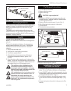
Mantels
FP1325
Insert mantel
height
4/1/03 djt
24" Min.
(610mm)
FP1325
Fig. 2 Minimum mantel height above fireplace.
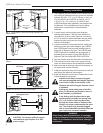
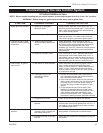
Framing & Finishing
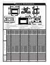
For Zero Clearance Kit applications, it is important to
determine the finished facing material before beginning
to frame. This will allow for the thickness of the finishing
material between the frame and the fireplace trim.
Similarly, consideration must be given to the 1" inch
depth of the air inlet channel sitting on the fireplace
base. Finishing material for the hearth should be flush
with the top of the air inlet channel.
If the fireplace is installed at floor level a noncombus-
tible hearth must extend a minimum 12" (305mm) in
front of the fireplace.
If the fireplace is recessed into the wall and at least 12"
(305mm) above floor level, no hearth is required.
The use of wallpaper adjacent to this fire-
place is not recommended as high tem-
peratures given off by this fireplace may
adversely effect the binders in the adhe-
sive used to apply the wallpaper.
NOTE: Insulating around the fireplace will result in
overheating and possible malfunctioning of the circulat-
ing fan.
Zero Clearance Applications
An alternate air supply is recommended
with this component.
For installation other than in existing wood-
burning fireplaces such as new construction or renova-
tion projects, a Zero Clearance Kit must be used. The
kit enables these inserts to be installed in combustible
environments. Whenever using a Zero Clearance Kit,
consideration must be given to the dimensions of the
Zero Clearance Kit and the requirements of the Air Kit.
NOTE: If a Zero Clearance Kit is required for mod-
els LHEC20/LHER20/LHEC30/LHER30 Natural Vent
Inserts, only the CFM Corporation zero clearance
kit HEZC is approved to be used. When using the
HEZC with insert models LHEC20 or LHER20, the
Trim Closure Kit, LHE20TCK, must also be installed.
35"
(889mm)
37¹⁄₄" (946mm)
FP1251
Insert framing
and finishing
1/03
27¹⁄₄" (692mm)
19¹⁄₈"
(486mm)
Air Inlet Channel
Drywall
Finish Wall
Decorative Trim Kit
FP1351
Fig. 3 LHE insert framing dimensions.