


14 CY3270 PSoC® FirstTouch™ Guide, Document # 001-15945 Rev. **
Getting Started
2.5.3 Simulating the Project
Simulation is a very useful tool. You can run the simulation on the project you defined; if the results
are not what you expected, you can go and change the design until you get the results you want.
This saves time and effort by allowing evaluation of your design's operation prior to programming the
hardware.
Once you have made changes to your project, click the Simulation tab to proceed to the PSoC
Express Design Simulator to verify that your design does what you intended. For instance, type 23 in
the CSD Properties ‘Current Value’ box and see the ‘Red’ come up in the LED ‘Current Value’ box.
This matches the transfer function logic designed into this project.
If the behavior meets your expectations, you are ready for the next step. If not, you can go back to
the Design tab, edit the Transfer Function logic, and return to Simulation to verify your changes.
Other PSoC evaluation and development kits implement monitoring and tuning to change project
variables in real-time and then dynamically change the driver configuration.
2.5.4 Building the New Project
Once you are confident that your design is correct, from the top menu bar click Build and then select
Generate/Build {your project name} Project.
2.5.4.1 Selecting the Target Device
PSoC Express displays a Device Selection window that allows you to select a ‘target’ device for your
project. All FTMF Expansion Card projects must use the 32-pin CY8C21434 as the device target.
Select this device from the list and click Next. Express then continues to compile your project.
2.5.4.2 Specifying the Target Device Pinout
The Express Pin Editor window appears. This window allows you to drag and drop the various
project signals to the PSoC device IO pins. For this project, no changes are made to the pin assign-
ments. Click Next to continue.
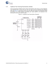
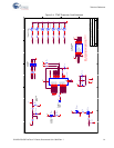
Note If you are creating your own project for the FTMF card, refer to the Figure 3-4 on page 21 for a
schematic and Table 3-1 on page 22 for the pin connections before proceeding beyond this point.
Once PSoC Express completes building your design, the BOM/Schematic window appears. Use this
as an error-checking step to confirm that all of the IO pins did not move and are exactly where you
intended.
2.5.5 Programming the Project
To program the project to the FTMF Expansion Card, do as follows:
1. From the top menu bar, click Program and then select PSoC Programmer. The PSoC Program-
mer utility launches.
2. On the Programmer GUI, select Port > FirstTouch.
3. Ensure that the Device Family is set to 21X34 and the Device Type is CY8C21434-24LFXI (this is
the PSoC on the FTMF Expansion Card).
4. Set the Programming Mode button to Reset and then click the Program button.
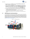
The Programmer utility begins programming the project’s HEX file to the FTPC bridge; the bridge in
turn re-programs the PSoC on the FTMF Expansion Card.