CY3270 PSoC® FirstTouch™ Guide, Document # 001-15945 Rev. ** 17
3. Technical Reference
3.1 FTPC Bridge Details
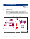
The FTPC Bridge is the interface bridge between the expansion cards, your PC, and the various
applications such as PSoC Express™, PSoC Designer™, and the PSoC Programmer utility.
Since the FTPC Bridge enumerates as a special type of ‘combo device’ that contains a PSoC Mini-
Prog interface, the standard PSoC Programmer utility can identify and communicate with the FTPC
bridge. This ensures that your FirstTouch Kit is automatically compatible with both PSoC Express
and PSoC Designer.
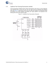
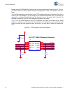
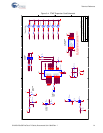
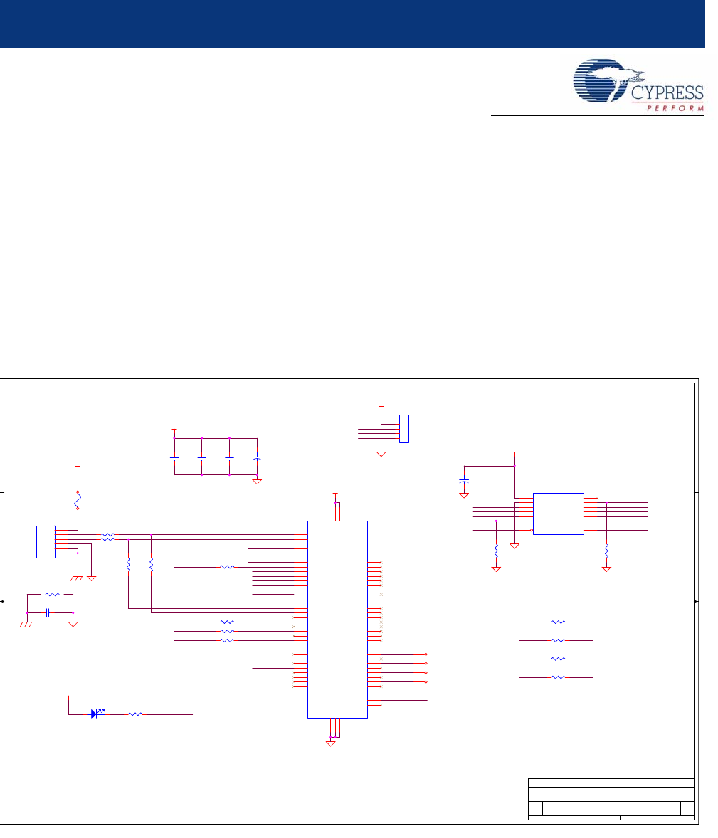
The schematic for the FTPC Bridge shown in Figure 3-1 is found on the CD included in the kit.
Figure 3-1. FTPC Bridge Schematic
5
5
4
4
3
3
2
2
1
1
D D
C C
B B
A A
8x2 0.100" FEMALE Expansion Receptacle
ISSP-RADON
ISSP-RADON
ISSP-RADON
Resettable Fuse
PCB: PDCR-9403
NO LOAD
REF-14210 **
FIRST TOUCH PC BRIDGE
B
11Thursday, June 21, 2007
Title
Size Document Number Rev
Date: Sheet
of
CYPRESS SEMICONDUCTOR © 2007
XRES894
ISSP_DAT
SPI_nSS
P02
P04
P03
P05
ISSP_XRES
ISSP_CLK
GPIO5
GPIO4
GPIO3
GPIO2
SCL_SCLK
SDA_MOSI
DETECT
ISSP_XRES
ISSP_CLK
ISSP_DAT
SPI_MISO
SPI_nSS
TYPE
XRES894
CLK894
DAT894
CLK894
DP
DM
DAT894
SPI_MISO
SDA_MOSI
SCL_SCLK
DETECT
TYPE
LED_ALIVE
LED_ALIVE
GPIO4
GPIO3
GPIO2
GPIO5
P03
P04
P05
P02
V50
V50
V50
V50
V50
V50
0805
R4 27
0805
R1 Zero
0805
R8
100
0805
R13 1K
0805
R12
NO LOAD
0805
C2
0.1 uFd
J1
ISSP894
1
2
3
4
5
TP4
0805
R3
100K
0805
R5 27
1206L
F1
350mA
0805
C6
0.01 uFd
0805
R14 Zero
TP0
RADIAL
D1
LED Blue
1 2
J3
8X2 PIN RECPT RA
1
3
5
7
9
11
4
13
15
6
8
2
16
14
12
10
VEXP_IN
GND
ISSP_XRES
ISSP_CLK
ISSP_DAT
EXP_TYPE
VEXP_OUT
MISO
SPI_nss
SDA-MOSI
SCL-SCLK
VLOCAL
GPIO2
GPIO3
GPIO4
GPIO5
0805
C4
0.1 uFd
0805
R15 Zero
TP6
0805
R10
NO LOAD
0805
R2
100K
U1
CY8C24894 QFN56
18
17
16
15
41
2
42
1
43
56
44
55
36
45
54
46
53
47
50
19
33
10
34
9
35
8
7
37
6
38
5
39
4
40
3
29
14
30
13
52
48
51
20
22
25
26
27
28
21
49
31
12
32
11
24
23
57
P1_1
P1_3
P1_5
P1_7
P2_0
P2_1
P2_2
P2_3
P2_4
P2_5
P2_6
P2_7
XRES
P0_0
P0_1
P0_2
P0_3
P0_4
GND2
GND1
P3_0
P3_1
P3_2
P3_3
P3_4
P3_5
P3_7
P4_0
P4_1
P4_2
P4_3
P4_4
P4_5
P4_6
P4_7
P5_0
P5_1
P5_2
P5_3
P0_5
P0_6
P0_7
DP
VDD1
P1_0
P1_2
P1_4
P1_6
DM
VDD2
P5_4
P5_5
P5_6
P5_7
P7_0
P7_7
EPAD
0805
R7
100
J2
USB A RA PLUG SMD
1
2
3
4
5
6
VBUS
DM
DP
GND
S1
S2
0805
R9
NO LOAD
+
A
C1
22 uFd 10v
TP2
0805
R16 Zero
0805
C3
0.1 uFd
0805
R11
NO LOAD
+
A
C5
10 uFd 10v
0805
R6 100K


