


4
Installation Specifications
WARNING
Observe all governing codes and ordinances during •
planning and installation. Contact your local building
department for further information.
To prevent an electric shock hazard, the power supply •
must meet the specifications stated below. It is the
owner’s responsibility to make sure that the electrical
service meets electrical requirements and that the
electrical outlet has been properly installed by a
licensed electrician.
Electrical Power Supply Requirements
The range is supplied with a factory installed, 6 foot •
long, power cord with a three-prong grounding plug.
It is connected to the chassis at the rear of the range.
It must be connected to a dedicated, grounded three-
prong electrical outlet installed by a licensed electrician.
The electrical installation, including minimum supply •
wire size and grounding, must be done in accordance
with National Electric Code ANSI/NFPA 70* and local
codes and ordinances. A copy of this standard may be
obtained from:
National Fire Protection Association
1 Batterymarch Park
Quincy, Massachusetts 02269-9101
The correct voltage, frequency and amperage must be •
supplied to the electrical outlet according to the product
data label located on the top of the kick plate under the
door. Remove the door to view the data label (see
page 9). See the Electrical Supply Requirements
table below for reference.
Electrical Circuit
Required
Total Connected Load
120 Vac 60 Hz,
15 Amp.
120 Vac 60 Hz,
5.0 Amp.
Electrical Supply Requirements
IMPORTANT: The above information is for reference only.
If the information above differs from the information on the
product data label on the appliance, use the information on
the label.
Gas Supply Requirements
Be certain that the range being installed is correct for •
the gas service being provided (natural gas or LP gas).
Check your local building codes for the proper method •
of installation. In the absence of local codes, this
appliance should be installed in accordance with the
National Fuel Gas Code ANSI Z223.1/NFPA 54.
An external manual shut-off valve must be installed •
between the gas inlet and the range for the purpose of
turning on or shutting off gas to the appliance.
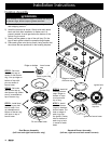
The cooktop comes from the factory with the regulator •
installed. Use only the installed regulator. The inlet
accommodates a 3/4” gas line. The range ships with a
1/2” to 3/4” adapter connected to the regulator.
Gas
Type
Manifold
Pressure*
(WC)
Min. Gas Supply
Pressure (WC)
Max. Input
Pressure
Natural 5” 6” 1/2 p.s.i.
LP 10” 11” 1/2 p.s.i.
Gas Supply Requirements
* The gas supply pressure for testing the regulator setting
shall be at least 1 inch water column (249Pa) above the
specified manifold pressure.
IMPORTANT: The information above is for reference only.
If the above data does not agree with the product data
label, use the data on the product data label on top of the
kick plate below the door (remove the door according to the
instructions on page 9 to view it).
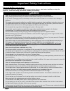
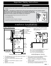
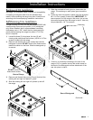
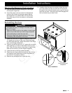
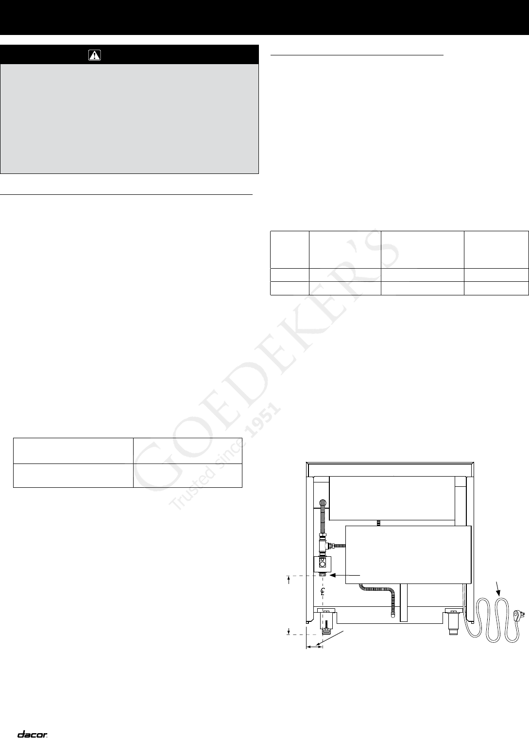
The gas connection is located on the back of the unit
as shown below. Use a 1/2” male NPT to connect to the
regulator.
15 7/8”
(403 mm)
to
18”
(457 mm)
3 3/4”
(95 mm)
Power cord
Gas
connection