


6
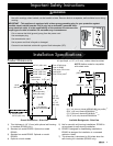
Installation Specifications
Installation Instructions
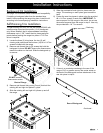
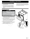
Verifying the Package Contents
Unpack the range and verify that all required parts have
been provided. If any item is missing or damaged, please
contact your dealer immediately. Do not install a damaged
or incomplete appliance. The customer must report
cosmetic issues immediately to the dealer or builder.
WARNING
Observe all governing codes and ordinances during •
planning and installation. Contact your local building
department for further information.
I• f the gas or electric service provided does not meet
the product specifications, do not proceed with the
installation. Call the selling dealer, the gas supplier or
a licensed electrician.
This appliance must be installed by a licensed •
plumber or gas fitter when installed within the
Commonwealth of Massachusetts.
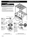
Parts List
Anti-tip bracket•
Grates (2) 12 inch, (1) 10 inch•
Use and care manual•
Ignitor cleaning brush•
Lens pry stick•
Stainless steel cleaner•
Dual burner rings (2)•
Outer dual burner caps (2)•
Inner dual burner caps (2)•
Standard burner caps (2) large, (2) small•
Standard burner rings (2) large, (2) small•
Oven racks (3)•
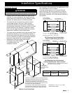
The following parts are are included with model ER36GI
only. They are for use with self-rimming installations:
3 Self-rimming trim pieces (left, right, rear)•
2 Self-rimming side panels (left, right)•
13 #8 x 1/4 Torx screws•
See the use and care manual for a list of other optional
accessories and parts.
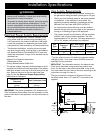
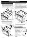
Gas and Electrical Locations
The installation must allow for the following:•
Access to the gas shut-off valve when the unit is ◊
installed.
Access to the electrical outlet, when the range is in ◊
place.
The gas supply piping, gas shut-off valve and the ◊
electrical junction box or receptacle must be located
so they do not interfere with the range when it is
installed.
The electrical outlet and gas shut off valve must ◊
be located so that the range can be pulled out for
service while the appliance remains connected.
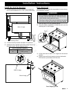
Both the gas supply piping and shut-off valve and the •
electrical outlet must be located so they do not interfere
with the range when it is installed.
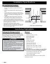
Existing utility connections may be used for •
replacement purposes, provided they meet local code
and fit within the utility clearance area at the back of
the range (see diagram, right).
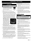
Utility Clearance Behind Range
C
L
C
L
12 1/2” (318 mm)
15” (381 mm)
12” (305mm)
2 1/2”
(64mm)
3 1/2”
(89mm)
1” (25mm)