


5
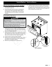
Installation Specifications
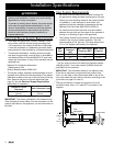
Any openings in the wall behind the appliance or in the •
floor underneath it must be sealed.
If cabinet storage space is to be provided directly •
above the range, the risk of personal injury may be
reduced by installing a ventilating hood that projects
horizontally a minimum of 5 inches beyond the face of
the cabinets.
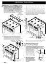
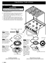
Cabinet Layout
WARNING
Failure to meet or exceed the maximum and minimum
dimensions/clearances stated may result in a fire hazard.
Carefully check the location where the range is to be •
installed. For best performance, the range should be
placed away from drafts that may be caused by doors,
windows and heating and air conditioning outlets.
To reduce the risk of personal injury and to reduce •
accumulated smoke in the room, Dacor strongly
recommends installing a range hood. A range hood
should project horizontally a minimum of five (5) inches
beyond the face of the cabinets. If installing a range
hood, see the range hood specifications for minimum
clearances in addition to those stated below.
The range may be installed flush to the rear wall. • Dacor
recommends installing a non-combustible material on
the rear wall above the range and up to the vent hood.
It is not necessary to install non-combustible materials
behind the range below the countertop height.
Regardless of the type of back wall surface, •
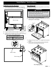
Note 2
2
Cabinet/countertop depth is at discretion of customer
but cabinet face SHALL NOT protrude further than rear
of front panel. See product dimesions.
3
Consult local code for exact location requirements.
4
Not applicable for cabinets more than a horizontal
distance of 10” (254mm) from the edge of the range.
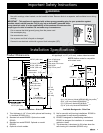
1
Vertical to combustible surface from range grate level;
if installing an overhead vent hood, also check the hood
specifications for minimum required clearances.
B
A
Non-combustible
surface along
back wall
recommended
10” (254mm Min.
to combustible side
walls above the range
(both sides)
Top of
finished
counter
Suggested
location of
utilities
3
30” (762mm)
Min.
1
13” (330mm)
Max.
4
18” (457mm)
Min.
1, 4
C
A
6
B C
36” minimum
(914 mm)
36” (914 mm)
minimum
37 1/8” (943 mm)
maximum
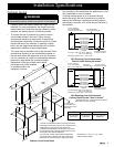
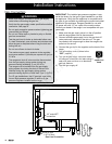
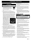
Cabinet Cutout Dimensions
Self-Rimming Cutout Dimensions -
Cabinet Depth Greater Than 24 Inches
5
Self-Rimming Cutout Dimensions -
Cabinet Depth Exactly 24 Inches
5
non comubustible
rear wall recommended
Countertop Height: Min: 35 1/2” (902 mm)
Max: 37 5/8” (956 mm)
Countertop Thickness: Max: 1 5/8” (41mm)
countertop opening
35 1/4” (895 mm)
36” (914 mm)
cabinet opening
below countertop
below countertop
Cabinet face
Notch countertop
overhang to width of
cabinets
10” Min. (254mm)
to any combustibles
above counter both sides
Countertop overhang
2 1/8” (54 mm) Max.
24”
(610mm)
rear wall or
countertop edge
Countertop Thickness: Max: 1 5/8” (41mm)
countertop opening
cabinet opening
below countertop
below countertop
Cabinet face
Notch countertop
overhang to width of
cabinets
3/4” Min. (19mm)
Countertop overhang
10” Min. (254mm)
to any combustibles
above counter both sides
Countertop overhang
2 1/8” (54mm) Max.
24 1/8”
(613mm)
Countertop Height: Min: 35 1/2” (902 mm)
Max: 37 5/8” (956 mm)
35 1/4” (895 mm)
36” (914 mm)
5
Model ER36GI only. Included self-rimming trim kit
allows trim to overlap countertop.
6
See cutout dimensions above for self-rimming installations.
All tolerances: +1/16”, -0 (+1.6, -0 mm)
unless otherwise stated
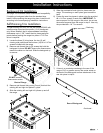
the range must not be installed
or operated without the
backguard in place.