22 Dell Latitude L400 Service Manual
2. Remove the display assembly.
3. Remove the keyboard assembly.
4. Remove the palmrest assembly.
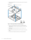
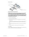
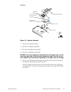
5. Remove the three M2 x 3.5-mm screws that secure the touch pad
assembly to the palmrest assembly (see Figure 16).
6. Slide the touch pad assembly out from under the two hold-down tabs.
7. Remove the touch pad assembly from the palmrest assembly.
8. Disconnect the flex cable from the ZIF connector on the back of the touch
pad (see Figure 16).
The flex cable remains attached to the touch pad holder assembly.
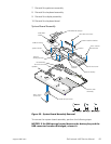
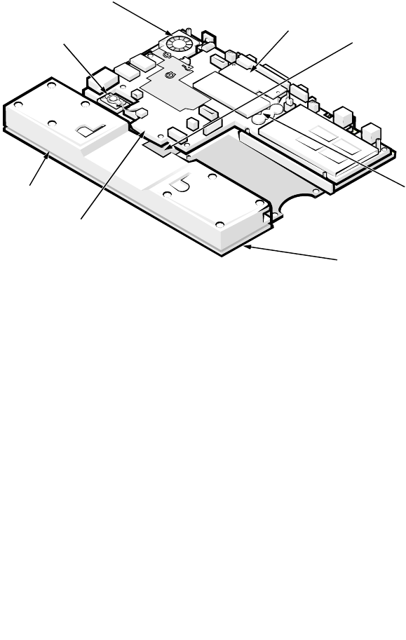
Bottom Assembly
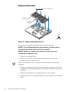
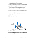
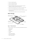
Figure 17. Bottom Assembly
The bottom assembly consists of the following field-replaceable components:
• Reserve battery
• Main battery
• Modem
• Fan assembly
• Speaker
• System board assembly
• Main battery release latch
• Bottom case assembly
reserve
battery
f
an
main battery
compartment
system board assembly
bottom
case cover
main battery release
latch location
modem
speaker (shown with audio
EMI shield removed)


