25
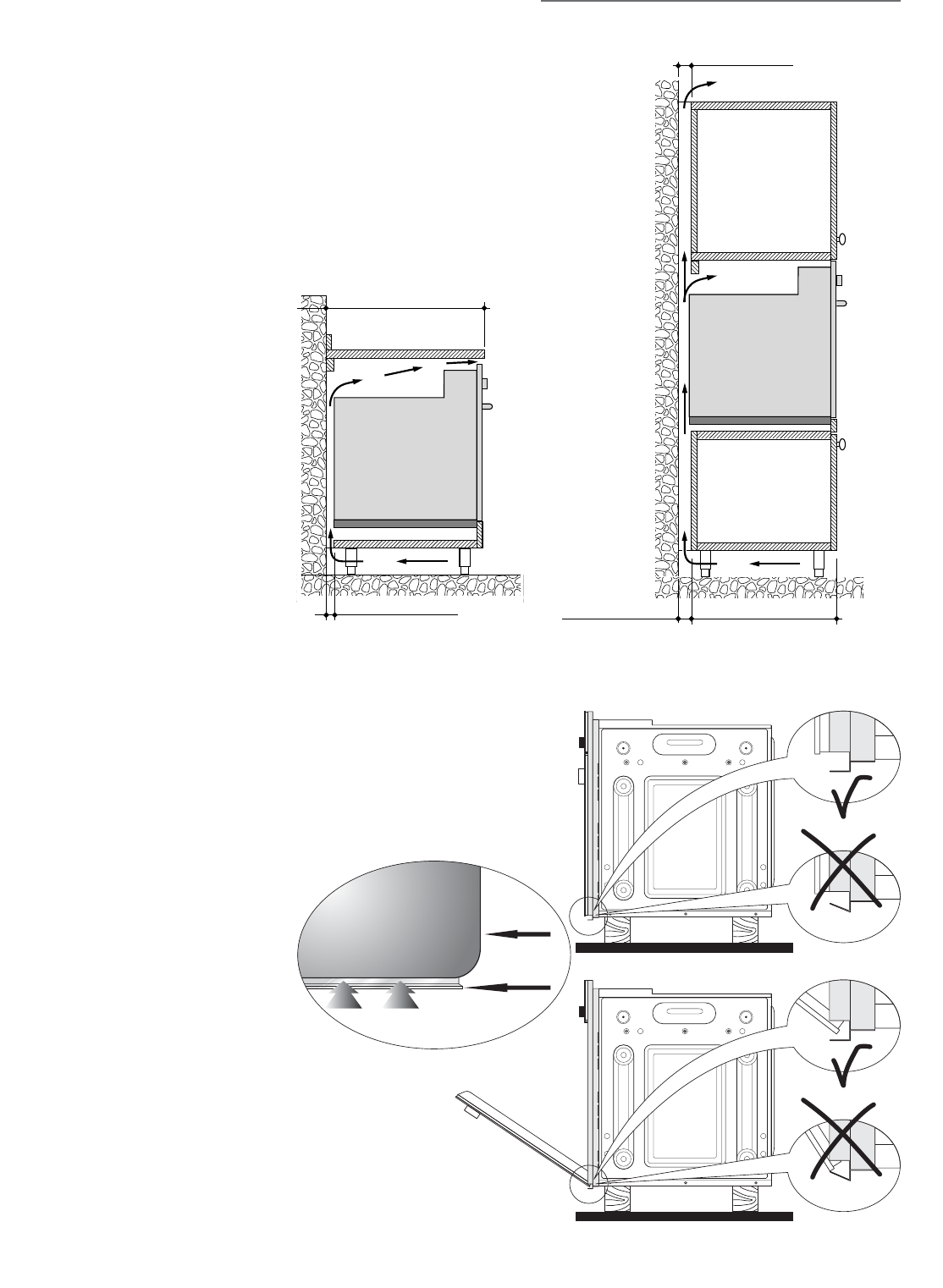
Fig. 5.4
1" 11/64 (30 mm)
23" 5/8 min (600 mm min)
1" 31/32 (50 mm)
1" 31/32 (50 mm) 21" 21/32 (550 mm)
Fig. 5.5
To ensure internal ventilation, aeration
channels must be provided as illustrated
in the figures 5.4 and 5.5.
The walls surrounding the oven must
be made of heat-resistant material.
Taking care NOT to lift the oven by the
door handle.
OVEN DOOR
LOWER TRIM
AIR FLOW
Fig. 5.6
IMPORTANT:
To avoid damage to the lower trim
please note the following instructions.
The lower trim is designed to allow for
good air circulation and the correct open-
ing of the oven door.
To ensure the trim is not damaged due to
the appliance being placed on the floor,
the appliance should be suitably support-
ed as in above illustrations.
After installation the appliance door
should be slowly opened to ensure no
damage has occurred.
No responsibility for lower trim dam-
age will be accepted if these instruc-
tions have not been followed.
ቦ


