


43
Descriptions and illustrations in this booklet are given as simply indicative. The manufacturer reserves
the right, considering the characteristics of the models described here, at any time and without
notice, to make eventual necessary modifications for their construction or for commercial needs.
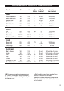
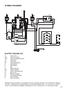
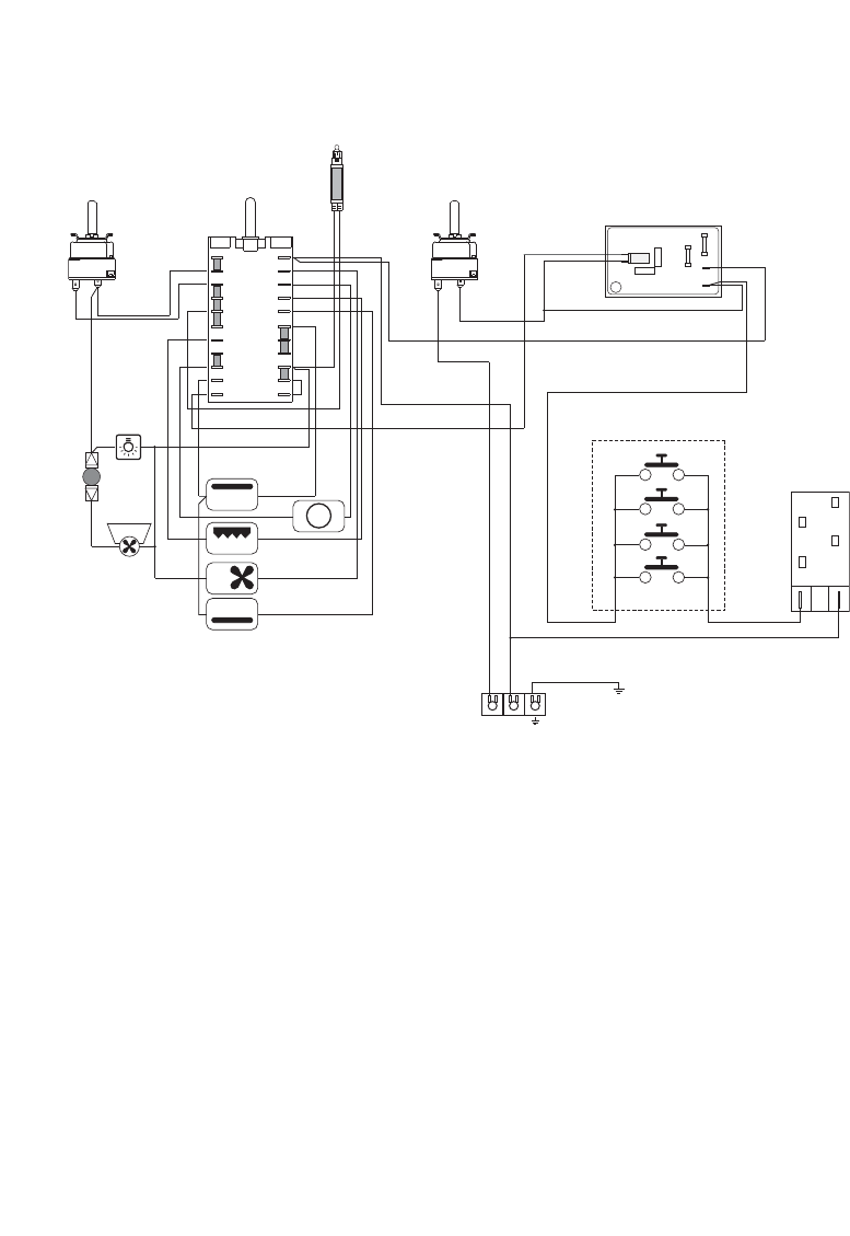
WIRING DIAGRAM
ELECTRIC DIAGRAM KEY
F1 Oven switch
TM Oven thermostat
TMS Oven thermostat (security)
LF Oven lamp
CF Cooling fan
PR Oven programmer
C Top element
G Grill element
V Fan
S Bottom element
CIR Circular element
PA Ignition switches group
A Ignition coil
TL Thermal overload
S1 Thermostat pilot lamp
M Terminal block
T Earth connection
TL
M
N
L
PA
A
T
1131797
N/7
1
1a
L/8
PR
S1
F1
1
6
1a
6a
4
9
4a
9a
3
8
3a
8a
2
7
2a
7a
5
10
11
5a
10a
11a
C
G
S
V
CIR
TM
CF
LF
TMS